Vibro-Acoustic Attenuation or Reduced Energy Transmission

a technology of vibration attenuation and energy transmission, applied in the field of vibration attenuation or energy transmission reduction, can solve the problems of affecting the ability of the panel to reduce noise and vibration levels, dispersing energy in a specific frequency region, and materials are very sensitive to contamination, so as to achieve the effect of reducing sound or energy transmission

Active Publication Date: 2014-01-30
KATHOLIEKE UNIV LEUVEN
View PDF26 Cites 28 Cited by
  • Summary
  • Abstract
  • Description
  • Claims
  • Application Information

AI Technical Summary

Benefits of technology

[0013]It is an object of embodiments of the present invention to provide good methods and devices for any of vibration and / or sound insulation, of sound absorption or of reduction of sound or energy transmission in at least one frequency range, as well as to provide good methods for manufacturing such devices.

Problems solved by technology

However, the high stiffness to mass ratio of these lightweight panels may result in unsatisfactory dynamic behaviour in that it may impair the panels' ability to reduce noise and vibration levels.
The mass of the air in the neck can resonate on the stiffness of the air cavity, causing dissipation of energy in a specific frequency region.
Although allowing very effective sound attenuation in certain frequency regions, these materials are very sensitive for contamination, since the characteristics of the connections between cavity and surrounding environment are crucial and may not be contaminated.
The degradation of performance due to contamination is the main weakness of methods as described in U.S. Pat. No. 7,854,298 B2 or JP2006337886 which are based on both Helmholtz resonances and acoustic impedance of material, which are both very sensitive for contamination.
This method however has the disadvantages of changing the mechanical properties of the structure, the addition of considerable weight to the structure and being difficult to manufacture.
This solution poses the same problems concerning weight and producability.
This because rather relying on localizing movement as in tuned vibrators, this method relies on the existence of localized modes which have imaginary acoustic wavelengths and are thus not able to radiate acoustically.
The main weakness of this method is that it is only effective for in-plane motion and thus not effective for tackling the common noise and vibration problems.
Furthermore the resonance of these structures relies again on a combination of materials which is difficult to produce.
The tuning of the attenuated frequencies will have a huge impact on the stiffness of the overall structure and the addition of high density spheres lead to a high increase of mass.

Method used

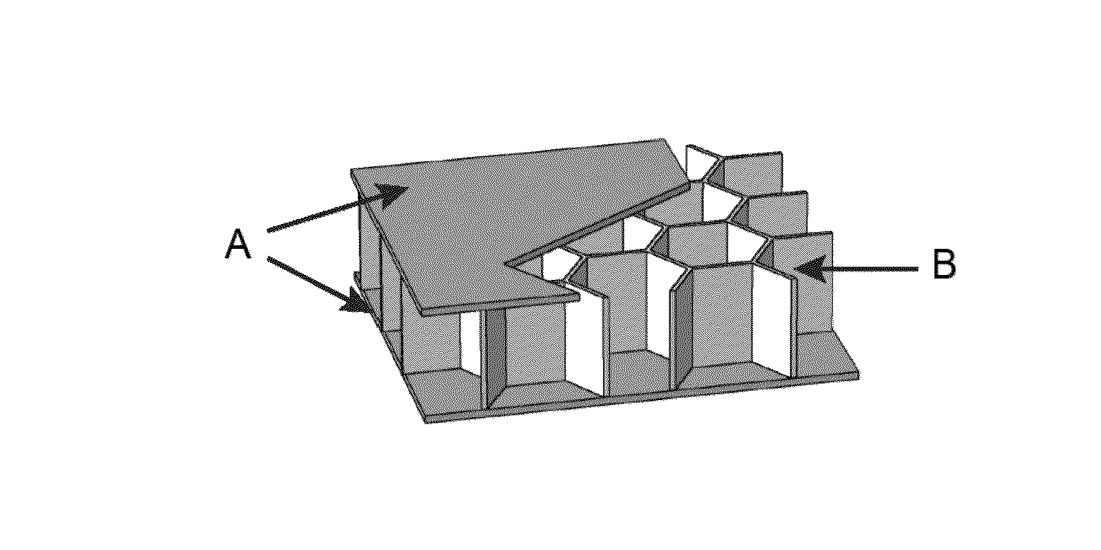
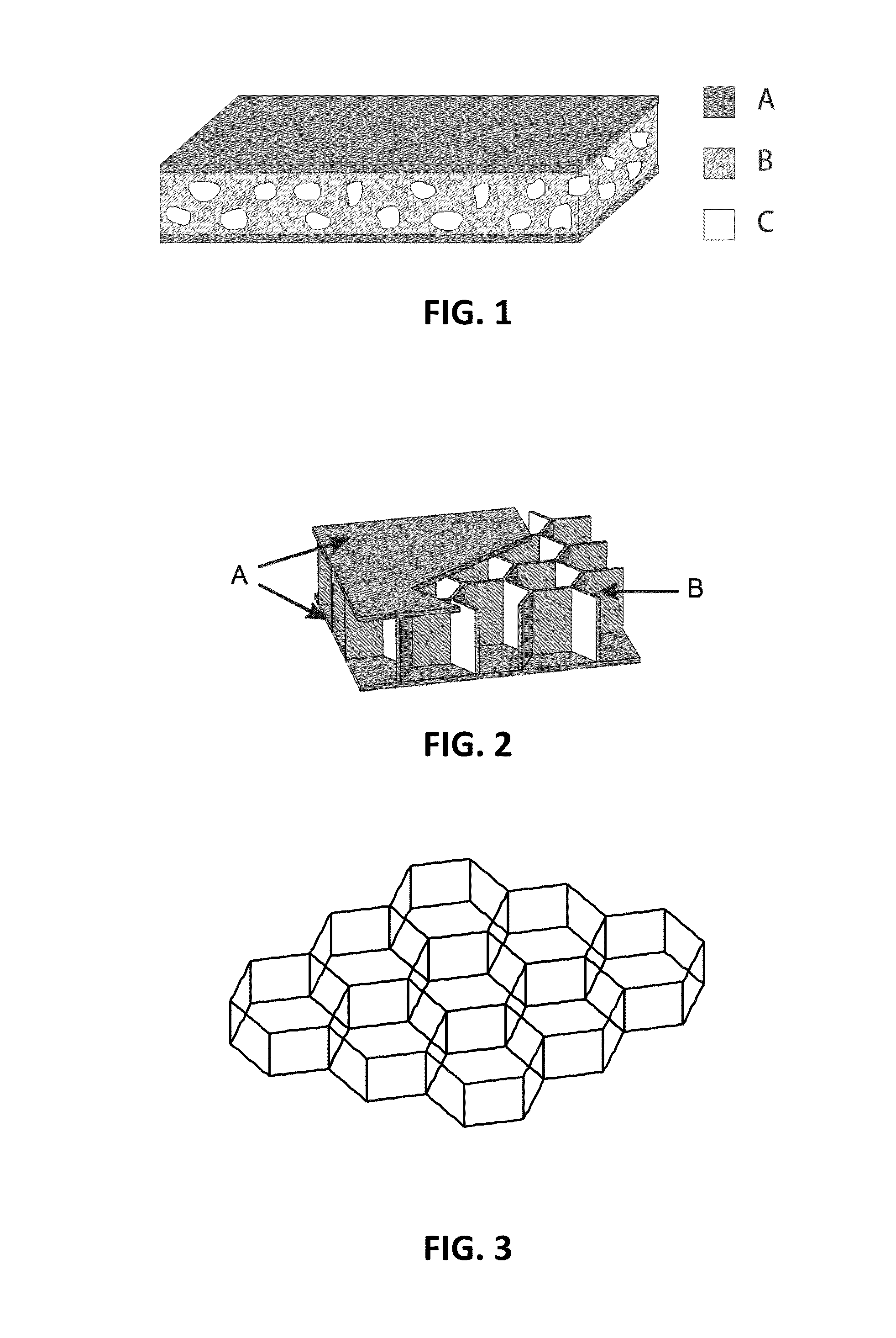
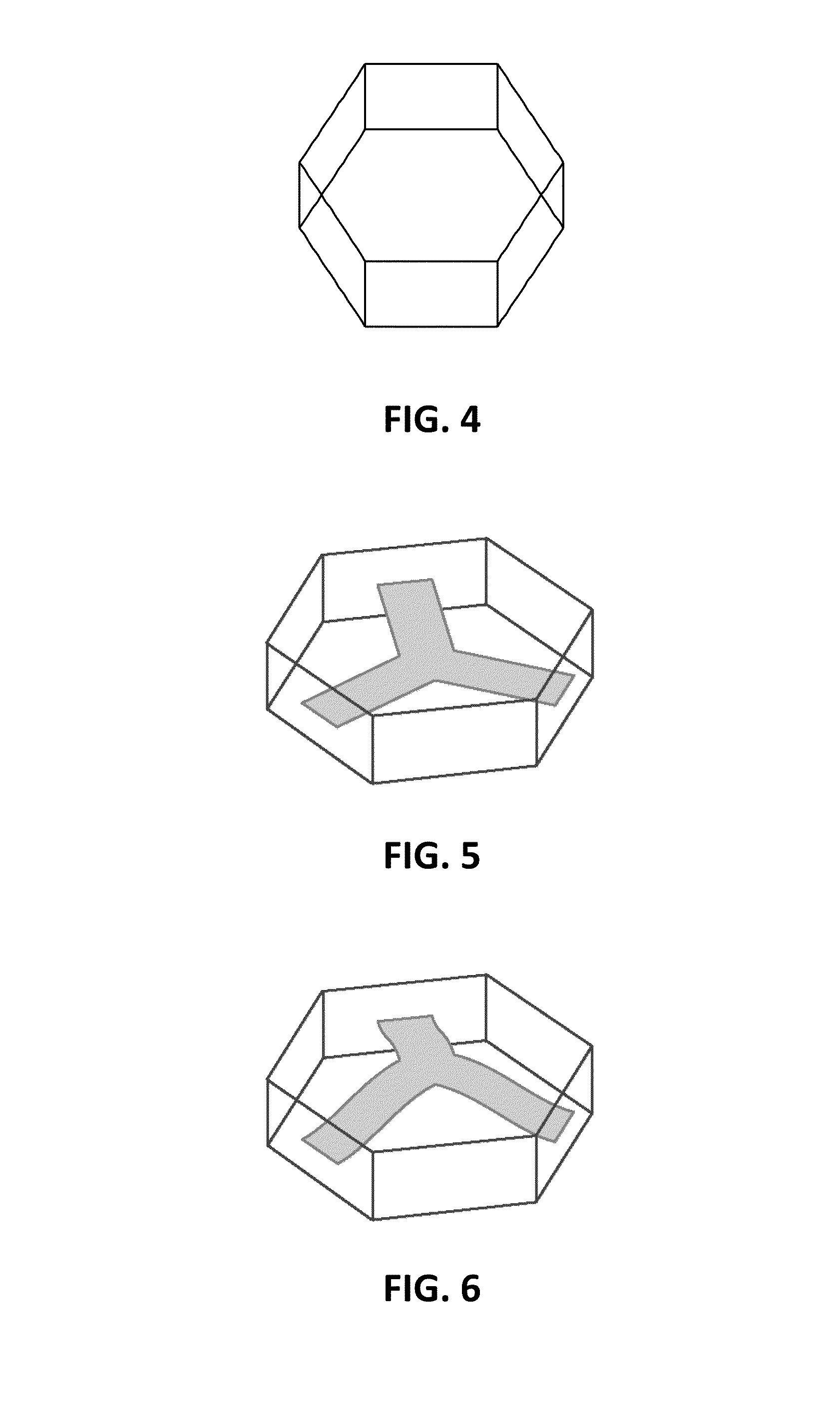

Image

  • Vibro-Acoustic Attenuation or Reduced Energy Transmission
  • Vibro-Acoustic Attenuation or Reduced Energy Transmission
  • Vibro-Acoustic Attenuation or Reduced Energy Transmission

Examples


Embodiment Construction

[0079]The present invention will be described with respect to particular embodiments and with reference to certain drawings but the invention is not limited thereto but only by the claims. The drawings described are only schematic and are non-limiting. In the drawings, the size of some of the elements may be exaggerated and not drawn on scale for illustrative purposes. The dimensions and the relative dimensions do not correspond to actual reductions to practice of the invention.

[0080]Furthermore, the terms first, second and the like in the description and in the claims, are used for distinguishing between similar elements and not necessarily for describing a sequence, either temporally, spatially, in ranking or in any other manner. It is to be understood that the terms so used are interchangeable under appropriate circumstances and that the embodiments of the invention described herein are capable of operation in other sequences than described or illustrated herein.

[0081]Moreover, t...


PUM


Abstract

Vibro-acoustic attenuation or reduced energy transmission. The present invention relates to devices that display frequency zones of strong vibro-acoustic attenuation or reduced energy transmission. This can be used in particular, although not necessarily solely, in applications that require lightweight materials with good mechanical properties and good vibro-acoustic response or in applications that require materials with high sound reflection, absorption or sound isolation in a certain frequency band.

Description

FIELD OF THE INVENTION[0001]The present invention relates to the field of vibro-acoustic attenuation and / or reduced energy transmission. More particularly the present invention relates to methods for vibro-acoustic attenuation or reduced energy transmission and to devices with cavities that display frequency zones of strong vibro-acoustic attenuation or reduced energy transmission. This can be used in particular, although not necessarily solely, in applications that require lightweight materials with good mechanical properties and good vibro-acoustic response or in applications that require materials with high sound reflection, absorption or sound isolation in a certain frequency band.BACKGROUND OF THE INVENTION[0002]Materials with cavities, such as e.g. honeycomb core panels, can combine excellent mechanical properties with a low mass, making them attractive for application in transport and machine design. However, the high stiffness to mass ratio of these lightweight panels may re...

Claims


Application Information

Patent Timeline
Patent Type & Authority Applications(United States)
IPC IPC(8): G10K11/00
CPCG10K11/002G10K11/172B33Y80/00
Inventor CLAEYS, CLAUSPLUYMERS, BERTDESMET, WIM
Owner KATHOLIEKE UNIV LEUVEN
Why Eureka
Try Eureka