EGR distribution and fluctuation probe based on co2 measurements

a co2 measurement and distribution technology, applied in the direction of material analysis, optical radiation measurement, instruments, etc., can solve the problems of increasing engine emissions, limiting the performance of the other cylinder, reducing the efficiency of the engine, so as to achieve the effect of increasing the development barrier, simple and cost-effective, and reducing the number of cylinders

Active Publication Date: 2014-02-06
UT BATTELLE LLC
View PDF1 Cites 17 Cited by
  • Summary
  • Abstract
  • Description
  • Claims
  • Application Information

AI Technical Summary

Benefits of technology

[0009]The present invention provides an EGR probe capable of providing rapid and accurate measurement of CO2 concentrations in a fluid stream, such as an engine intake manifold, intake runner or engine exhaust manifold. In one embodiment, the EGR probe is operatively coupled with a combined light source (a signal light source and a reference light source), a detector and a processor to provide a diagnostic system. The EGR probe of this embodiment includes a pitch optical cable (e.g., a hollow wave guide) that receives the light beam from the combined light source, a lens for focusing the light beam, a sampling chamber where the light beam passes through the fluid stream and a catch optical cable for conveying the light beam to the detector after it has passed through the sampling chamber. In one embodiment, the processor is configured to analyze the detector readings to determine CO2 concentration within the fluid stream.
[0013]In one embodiment, the EGR probe may include a mirror. The mirror may be disposed adjacent to the interior end of the probe to reflect the light beam from the pitch optical cable to the catch optical cable. The mirror may receive the light beam after it has passed from the pitch optical cable through the two flow cells and may reflect that light beam back through the two flow cells to the catch optical cable. As a result, the light beam may pass through each flow cell twice, thereby enhancing the absorption.
[0017]In an alternative embodiment, the present invention provides a diagnostic system that utilizes a laser light source. A laser light source may provide a variety of benefits over an LED light source. For example, a laser provides linear sensitivity over a wide CO2 range (e.g. CO2 absorption is generally linear with respect to CO2 concentration). A laser light source also has a narrow linewidth, which allows one to spectrally discriminate interfering species. It also allows simultaneous temperature and pressure measurements. For example, pressure may be determined based on broadening / narrowing of CO2 line, and temperature may be determined based on the relative absorption of two CO2 absorption transition with differing temperature dependencies of their absorption cross section. A laser light source may have more power and therefore may provide an improved signal-to-noise ratio, allow for faster measurements, and may enable multiple probes to be illuminated by a single light source. The use of multiple probes allows for measurements to simultaneously be taken at different locations to allow more extensive uniformity mapping and to accelerate validation and development.
[0023]In one embodiment, each light beam is amplitude modulated by attenuating the light beam at a frequency unique to that light beam. For example, the system may include a separate light chopper for each light beam. Each light chopper may be configured to introduce a unique modulation into the light beam, such as by effectively turning the light beam on and off at that light beam's unique modulation frequency.
[0024]The present invention provides a relatively simple diagnostic probe that is broadly applicable and suitable for use in applications with relatively severe packaging limitations. The EGR probe provides for the rapid processing of samples. As a result, the probe is capable of expanding development barriers. The use of a combined light source allows both signal and reference light beams to communicated through the probe using a single set of pitch and catch optics. Further, the combined light source allows the use of a single detector. The use of MIR LEDs provides a simple and cost effective combined light source that has appropriate absorption features for CO2. The use of hollow wave guides provides a mechanism for conveying MIR light without unacceptable losses. The present invention may provide a diagnostic system that is capable of producing the data necessary to achieve efficiency, durability and emissions targets for advanced engine systems, particularly those using high EGR.

Problems solved by technology

Internal combustion engines typically suffer from the ability to produce undesirable NOX emissions.
However, practically the EGR fraction can vary from cylinder to cylinder and cycle to cycle due to various spatial and temporal nonuniformities; e.g., non-ideal mixing, intake-manifold restrictions, and overlap of valve events with manifold resonating.
Such nonuniformities can cause one cylinder to reach a limit (e.g., incomplete combustion, etc.) earlier than the other cylinders, and can limit the performance of the other cylinders.
Ultimately, the result is lost efficiency and increased engine emissions.
Although a meaningful advance, conventional capillary probes suffer from a variety of disadvantages.
Perhaps most notably, capillary-probe-based diagnostic systems are not fast enough to measure fast valve-time scale, crank-angle resolved variations.
As a result, the use of capillary probes can place significant limitations on the capabilities the diagnostic system.
For the application of measuring EGR fraction distribution, they have limitations related to diffusion, temperature, and pressure.
Gas measurement required diffusion into the electrochemical cell and also through a protective porous housing (commonly ceramic based); the time required for the diffusion process can limit temporal response especially relative to rapid cylinder-to-cylinder and cycle-to-cycle time scales.
Also, the oxygen sensors must be heated to work effectively, and cool intake gas temperatures pose problems for the sensors to maintain the necessary sensor temperature.
Lastly, variations in pressure in the intake system (often occurring especially for boosted engines) can alter oxygen sensor measurements.

Method used


Image

  • EGR distribution and fluctuation probe based on co2 measurements
  • EGR distribution and fluctuation probe based on co2 measurements
  • EGR distribution and fluctuation probe based on co2 measurements

Examples


Embodiment Construction

Overview

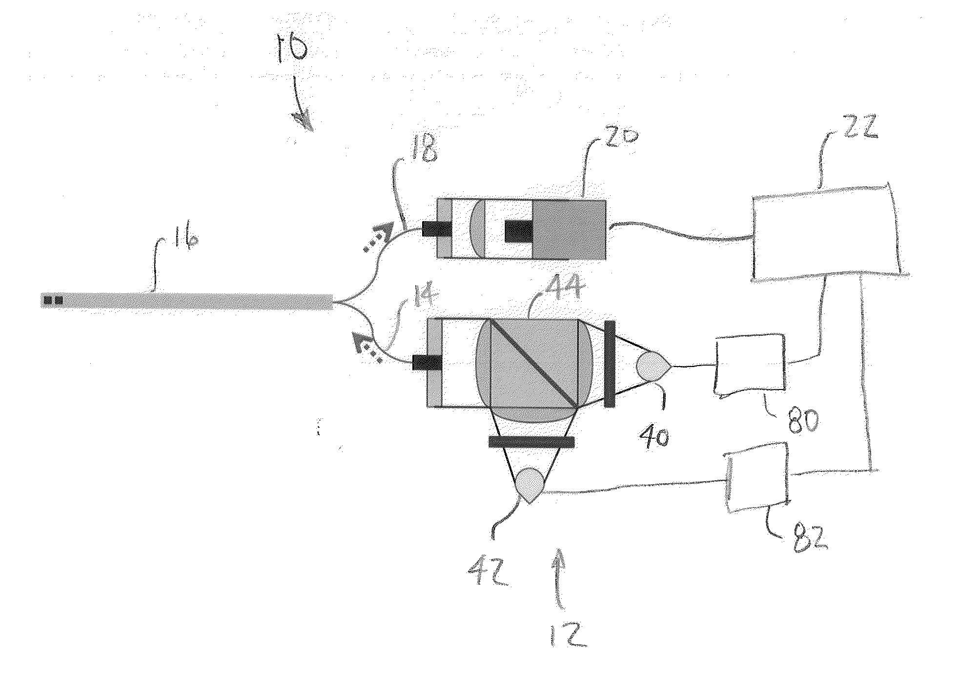
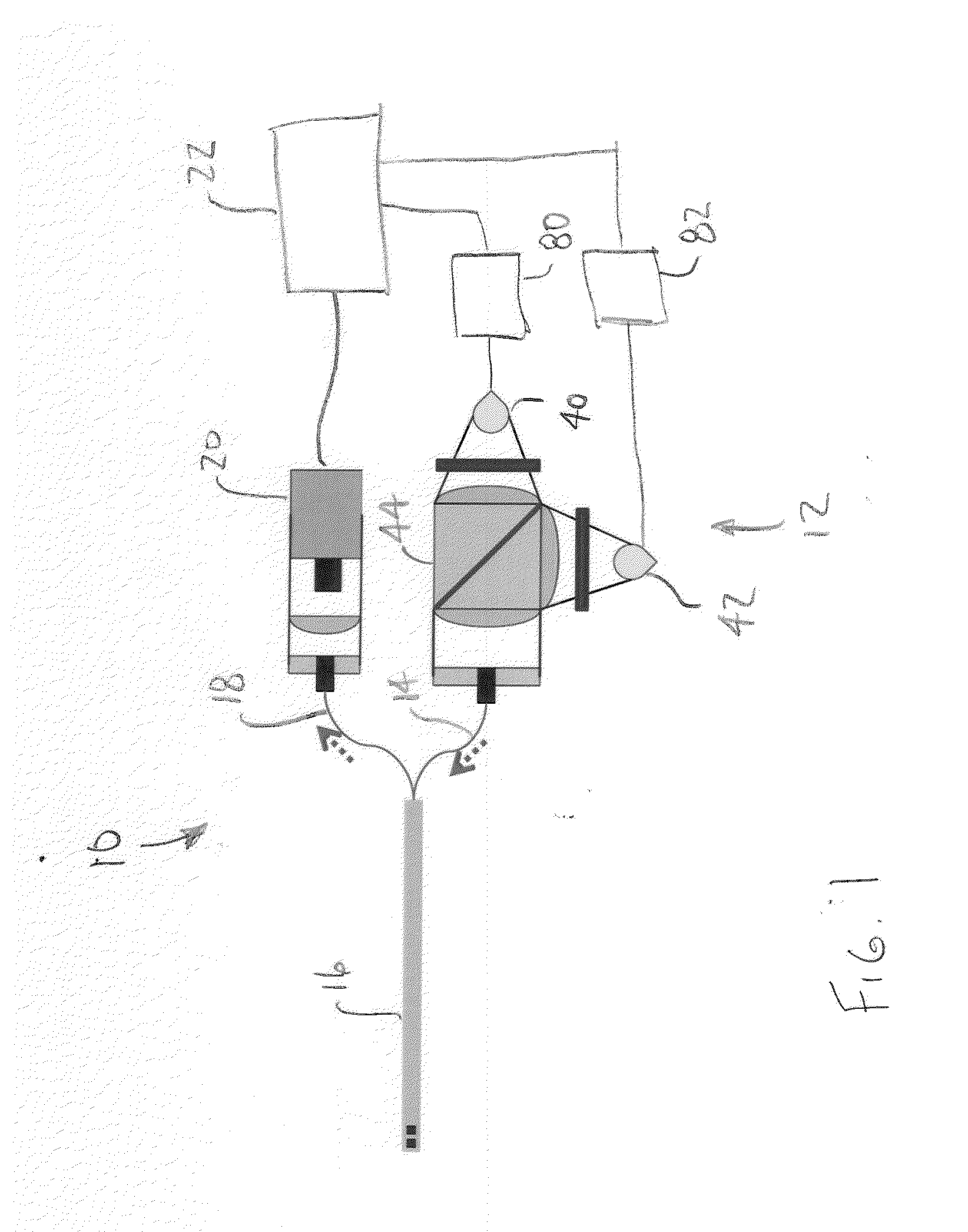
[0048]A diagnostic system in accordance with an embodiment of the present invention is shown in FIG. 1 and generally designated 10. The diagnostic system 10 of this embodiment permits accurate measurement of CO2 concentrations, and potentially other substances, within a fluid stream using absorption spectroscopy. The diagnostic system 10 generally includes a light source 12, a pitch optical cable 14, an EGR probe 16, a catch optical cable 18, a detector 20 and a processor 22 for determining CO2 concentration based on the output of the detector 20. The light source 12 may be a mid-infrared (MIR) light source having a signal source 40 and a reference source 42 that are combined into a single light beam. In use, the reference source 42 is used to normalize the measurements from the signal source 40. The EGR probe 16 of this embodiment is a single-port probe capable of being installed in a single opening, such as in an aperture in an intake manifold I or an exhaust manifold (not...


PUM

PropertyMeasurementUnit
frequenciesaaaaaaaaaa
modulation frequenciesaaaaaaaaaa

Abstract

A diagnostic system having a laser, an EGR probe, a detector and a processor. The laser may be a swept-λ laser having a sweep range including a significant CO2 feature and substantially zero absorption regions. The sweep range may extend from about 2.708 μm to about 2.7085 μm. The processor may determine CO2 concentration as a function of the detector output signal. The processor may normalize the output signal as a function of the zero absorption regions. The system may include a plurality of EGR probes receiving light from a single laser. The system may include a separate detector for each probe. Alternatively, the system may combine the light returning from the different probes into a composite beam that is measured by a single detector. A unique modulation characteristic may be introduced into each light beam before combination so that the processor can discriminate between them in the composite beam.

Description

CROSS REFERENCE TO RELATED APPLICATIONS[0001]This application is a continuation-in-part of U.S. application Ser. No. 13 / 912,462, entitled EGR DISTRIBUTION AND FLUCTUATION PROBE BASED ON CO2 MEASUREMENTS, filed Jun. 7, 2013, by Parks et al, which claims the benefit of U.S. Provisional Application No. 61 / 657,205, filed Jun. 8, 2012. U.S. Provisional Application No. 61 / 657,205 is incorporated herein by reference in its entirety.STATEMENT REGARDING FEDERALLY SPONSORED RESEARCH AND DEVELOPMENT[0002]This invention was made with government support under Contract No. DE-AC05-00OR22725 awarded by the U.S. Department of Energy. The government has certain rights in the invention.BACKGROUND OF THE INVENTION[0003]The present invention relates to internal combustion engine diagnostics and more specifically to apparatuses and methods for determining the spatial and temporal nonuniformities of CO2 in an intake fluid stream.[0004]Internal combustion engines typically suffer from the ability to produ...

Claims


Application Information

Patent Timeline
Patent Type & Authority Applications(United States)
IPC IPC(8): G01N21/35
CPCG01N21/3504
Inventor PARKS, II, JAMES E.PARTRIDGE, JR., WILLIAM P.YOO, JI HYUNG
Owner UT BATTELLE LLC
Why Eureka
Try Eureka