Control circuit and apparatus for digitally controlled oscillator

a control circuit and digital control technology, applied in the direction of electrical equipment, pulse automatic control, etc., can solve the problems of increasing current consumption, increasing manufacturing time and costs, and limited according to current source noise or accuracy

a control circuit and digital control technology, applied in the direction of electrical equipment, pulse automatic control, etc., can solve the problems of increasing current consumption, increasing manufacturing time and costs, and limited according to current source noise or accuracy

US20140035684A1Inactive Publication Date: 2014-02-06SAMSUNG ELECTRO MECHANICS CO LTD +1

Image

  • Control circuit and apparatus for digitally controlled oscillator
  • Control circuit and apparatus for digitally controlled oscillator
  • Control circuit and apparatus for digitally controlled oscillator

Examples


Embodiment Construction

[0038]Hereinafter, embodiments of the present invention will be described in detail with reference to the accompanying drawings. The invention may, however, be embodied in many different forms and should not be construed as being limited to the embodiments set forth herein. Rather, these embodiments are provided so that this disclosure will be thorough and complete, and will fully convey the scope of the invention to those skilled in the art. In the drawings, the shapes and dimensions of elements may be exaggerated for clarity, and the same reference numerals will be used throughout to designate the same or like elements.

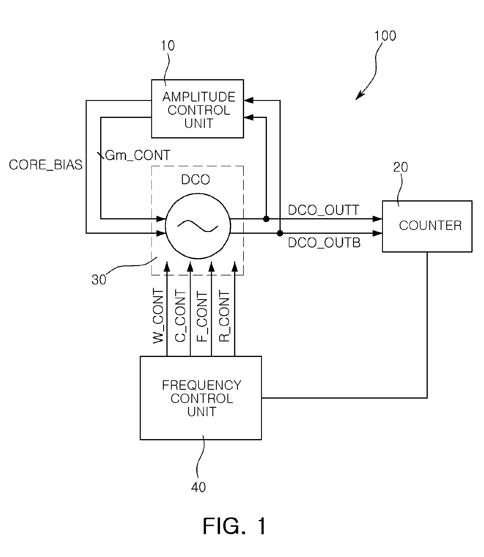
[0039]FIG. 1 is a block diagram schematically illustrating a control apparatus for a digitally controlled oscillator according to an embodiment of the present invention.

[0040]Referring to FIG. 1, a control apparatus 100 for a digitally controlled oscillator according to an embodiment of the present invention may include a digitally controlled oscillator core unit 30...


PUM


Abstract

There are provided a control circuit for a digitally controlled oscillator and a control apparatus for a digitally controlled oscillator using the same. The control circuit for a digitally controlled oscillator includes: a peak detection circuit detecting amplitude of a signal output from the digitally controlled oscillator; and a transconductance control circuit comparing an output of the peak detection circuit with a predetermined reference signal to control a transconductance value of a negative transconductance circuit included in the digitally controlled oscillator.

Description

CROSS-REFERENCE TO RELATED APPLICATIONS[0001]This application claims the priority of Korean Patent Application No. 10-2012-0084099 filed on Jul. 31, 2012, in the Korean Intellectual Property Office, the disclosure of which is incorporated herein by reference.BACKGROUND OF THE INVENTION[0002]1. Field of the Invention[0003]The present invention relates to a control circuit for a digitally controlled oscillator and a control apparatus for a digitally controlled oscillator using the same.[0004]2. Description of the Related Art[0005]A phase locked loop (PLL) circuit for generating a carrier frequency having applications in a 4th generation (4G) system such as the long term evolution (LTE) system, and the like, wireless connection in a cellular phone such as Bluetooth, a global positioning system (GPS) system, wideband code division multiple access (WCDMA), and the like, a wireless local area network (LAN) such as an 802.11a / b / g LAN, or the like, has been widely used. An analog type PLL c...

Claims


Application Information

Patent Timeline
06 Feb 2014
Publication
US20140035684A1
IPC
H03L5/00; H03L7/06
CPC
H03L7/06; H03L5/00; H03L7/08; H03L2207/50
Inventors
NA, YOO SAM; LEE, KANG YOON