Gasket for fuel cell system manifold seal

Active Publication Date: 2014-02-06
FUELCELL ENERGY INC
View PDF1 Cites 5 Cited by
  • Summary
  • Abstract
  • Description
  • Claims
  • Application Information

AI Technical Summary

Benefits of technology

[0016]The gasket has utility, for example, in fuel cell systems such as MCFCs for sealing a manifold to the fuel cell system to prevent leakage or gas through the gasket. The gasket also has mechanical properties suffic

Problems solved by technology

However, such conventional gaskets are pliable and tend to sag when handled or otherwise manipulated during an assembly process.
In addition, conventional gaskets have relatively low compressive strength.
For example, conventional gaskets can irreversibly crush and achieve a strain of almost 0.9 in/in, when subject to a relatively low compressive load, thereby degrading the gaskets' sealing performance.
A problem sometimes experienced by liquid phase fuel cells such as MCFCs is electrolyte migration which is characterized by the loss of the electrolyte from the positive end cell and the gain of electrolyte by the negative end cell.
This results in an irreversible increase in internal electrical resistance causing a significant voltage drop across the positive end cell and therefore decreasing the useful life of the MCFC stack.
Migration of the electrolyte towards the negative end cel

Method used


Image

  • Gasket for fuel cell system manifold seal
  • Gasket for fuel cell system manifold seal
  • Gasket for fuel cell system manifold seal

Examples


Embodiment Construction

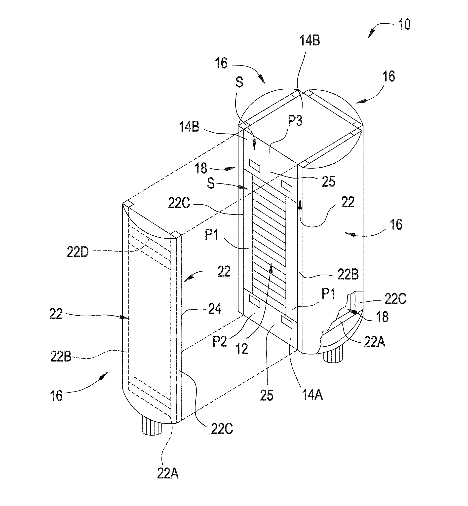
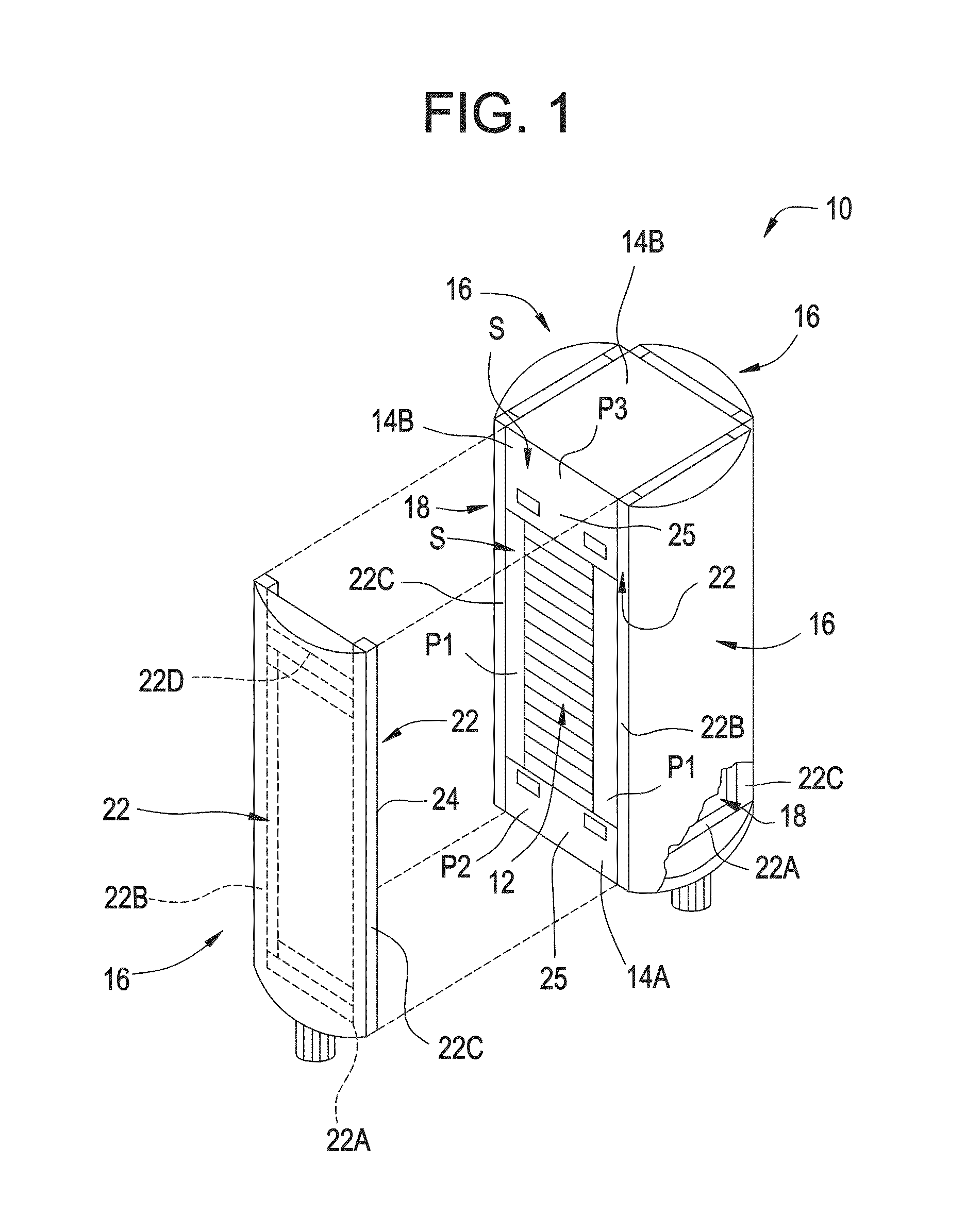
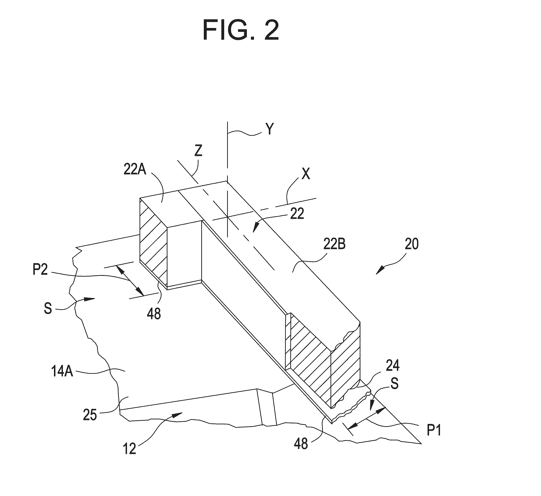
[0032]Referring to FIG. 1 a fuel cell system, generally designated by the numeral 10 includes a Molten Carbonate Fuel Cell (MCFC) stack 12 positioned between opposing end plates 14A and 14B. A manifold 16 is shown positioned on three of four outwardly facing surfaces 18 of the fuel cell system 10 for directing a fluid such as fuel or an oxidant into or out of the fuel cell stack. One of the manifolds 16 is shown removed from the outwardly facing surface 18 to illustrate the stack 12 and outward facing surface 18. When assembled all four manifolds 16 are positioned on one of the respective outwardly facing surfaces 18. A generally rectangular sealing area S extends around a peripheral portion of each of the outwardly facing surfaces 18. The sealing area S is defined by a peripheral area P1 of the fuel cell stack and portions P2 and P3 of the endplates 14A and 14B, respectively. Each of the manifolds 16 has a portion thereof secured to a portion of the portion P2 of the end plate 14A....


PUM


Abstract

A gasket for a manifold seal for a fuel cell system includes a first layer of fibrous ceramic material having a first compressibility, a second layer of fibrous ceramic material having a second compressibility and a third layer of fibrous ceramic material having third compressibility. The third layer of fibrous ceramic material is positioned between and engaged with the first layer of fibrous ceramic material and the second layer of fibrous ceramic material. The third compressibility is less than the first compressibility and less than the second compressibility.

Description

CROSS REFERENCE TO RELATED APPLICATIONS[0001]This application is a continuation in part of copending U.S. patent application Ser. No. 12 / 608,175 entitled “Fuel Cell System Manifold Seal,” filed Oct. 29, 2009 and of U.S. patent application Ser. No. 13 / 932,644 “Fuel Cell System Manifold Seal,” filed Jul. 1, 2013, which is a continuation of U.S. patent application Ser. No. 12 / 608,175, both of which are incorporated herein by reference in their entirety.FIELD OF THE INVENTION[0002]The present invention generally relates to a seal for use in a fuel cell system manifold and more specifically relates to composite gasket for sealing the manifold to the fuel cell system.BACKGROUND OF THE INVENTION[0003]A fuel cell is a device which uses an electrochemical reaction to convert chemical energy stored in a fuel such as hydrogen or methane into electrical energy. In general, fuel cells include an anode to catalytically react with the fuel and a cathode in fluid communication with an oxidant such ...

Claims


Application Information

Patent Timeline
IPC IPC(8): H01M8/02
CPCH01M8/0282H01M8/2485H01M2008/147Y02E60/50H01M8/04201H01M8/244
Inventor JIAN, TOM X.YUH, CHAO-YICHEN, LINGNEDU, DANIELA
Owner FUELCELL ENERGY INC
Why Eureka
Try Eureka