Control device for electric motor and control method for electric motor

a control device and electric motor technology, applied in the direction of motor/generator/converter stopper, dynamo-electric converter control, dynamo-electric gear control, etc., can solve the problems of reducing the efficiency of the electric motor, the output of the electric motor cannot be thereby improved, and the usage rate of the power supply voltage is reduced. , to achieve the effect of improving the efficiency and output of the electric motor and improving the power supply voltag

Active Publication Date: 2014-02-13
NISSAN MOTOR CO LTD
View PDF16 Cites 13 Cited by
  • Summary
  • Abstract
  • Description
  • Claims
  • Application Information

AI Technical Summary

Benefits of technology

[0008]The present invention has been proposed in view of the circumstances described above and an object thereof is to provide a control device for an electric motor and a control method for an electr

Problems solved by technology

However, the conventional drive control device for an AC electric motor described above does not determine whether the electric motor is stable or unstable in the over-modulation region and can thus perform only the simple control using the square wave.
This reduces the usage rate of a power supply voltage.
Accordingly, the conventional drive control device has a problem that the efficiency of the electric motor is reduced and the output of the electric motor cannot be thereby improved.
Moreover, the conventional drive control device has the following problems.
Since switching among the three control methods is performed between the normal modulation region and the over-modula

Method used


Image

  • Control device for electric motor and control method for electric motor
  • Control device for electric motor and control method for electric motor
  • Control device for electric motor and control method for electric motor

Examples


first embodiment

[0043][Overall Configuration of Control Device for Electric Motor]

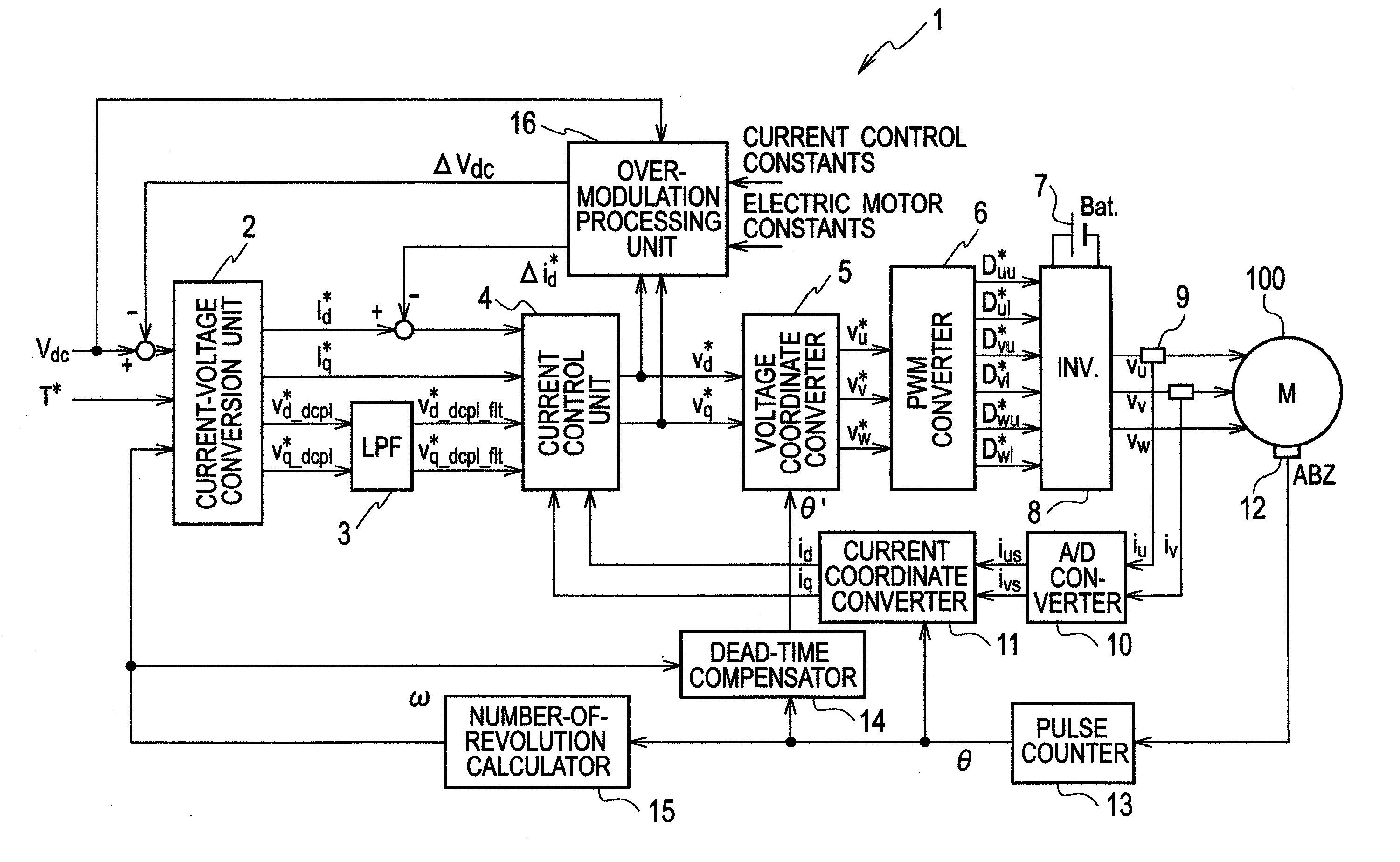
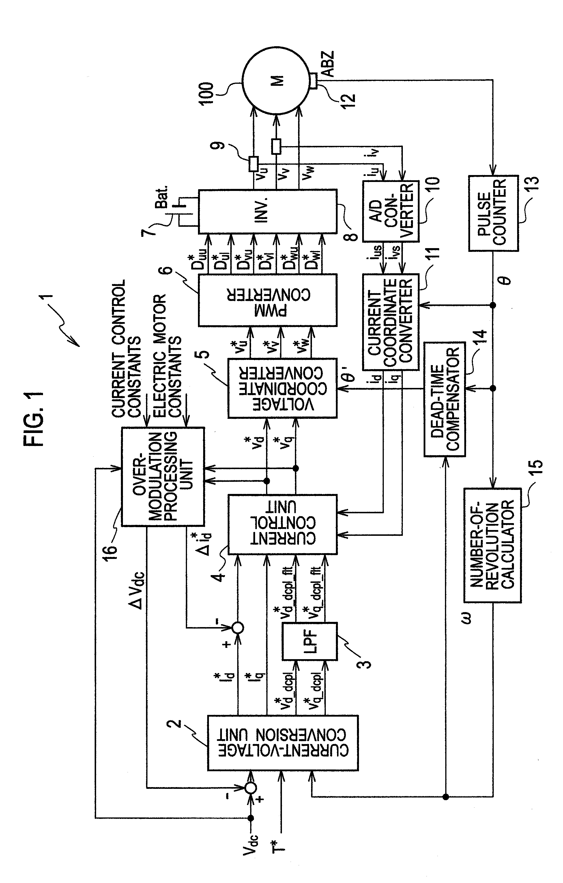
[0044]FIG. 1 is a block diagram showing an overall configuration of a control device for an electric motor in the embodiment.

[0045]As shown in FIG. 1, a control device 1 for the electric motor in the embodiment is a control device configured to control an electric motor 100 by current vector control and includes: a current-voltage conversion unit 2 configured to calculate a state quantity for voltage command value calculation from a torque command value T* by referring to a current-voltage conversion map stored in advance; a low-pass filter 3 configured to remove high-frequency components in d and q-axis non-interference voltage command values vd—dcp1*, vq—dcp1* outputted from the current-voltage conversion unit 2; a current control unit 4 configured to calculate d and q-axis voltage command values vd*, vq* used to drive the electric motor 100, on the basis of the state quantity for voltage command value calculation a...

second embodiment

[0096]Next, the second embodiment to which the present invention is applied is described with reference to the drawings. The same parts as those in the first embodiment described above are denoted by the same reference numerals and detailed description thereof is omitted.

[0097][Overall Configuration of Control Device for Electric Motor]

[0098]FIG. 7 is a block diagram showing a configuration of a control device for an electric motor in the embodiment. As shown in FIG. 7, a control device 71 for the electric motor in the embodiment includes the same constitutional elements as those in the control device 1 for the electric motor in the first embodiment which are shown in FIG. 1, but is different in inputs and outputs of an over-modulation processing unit 76.

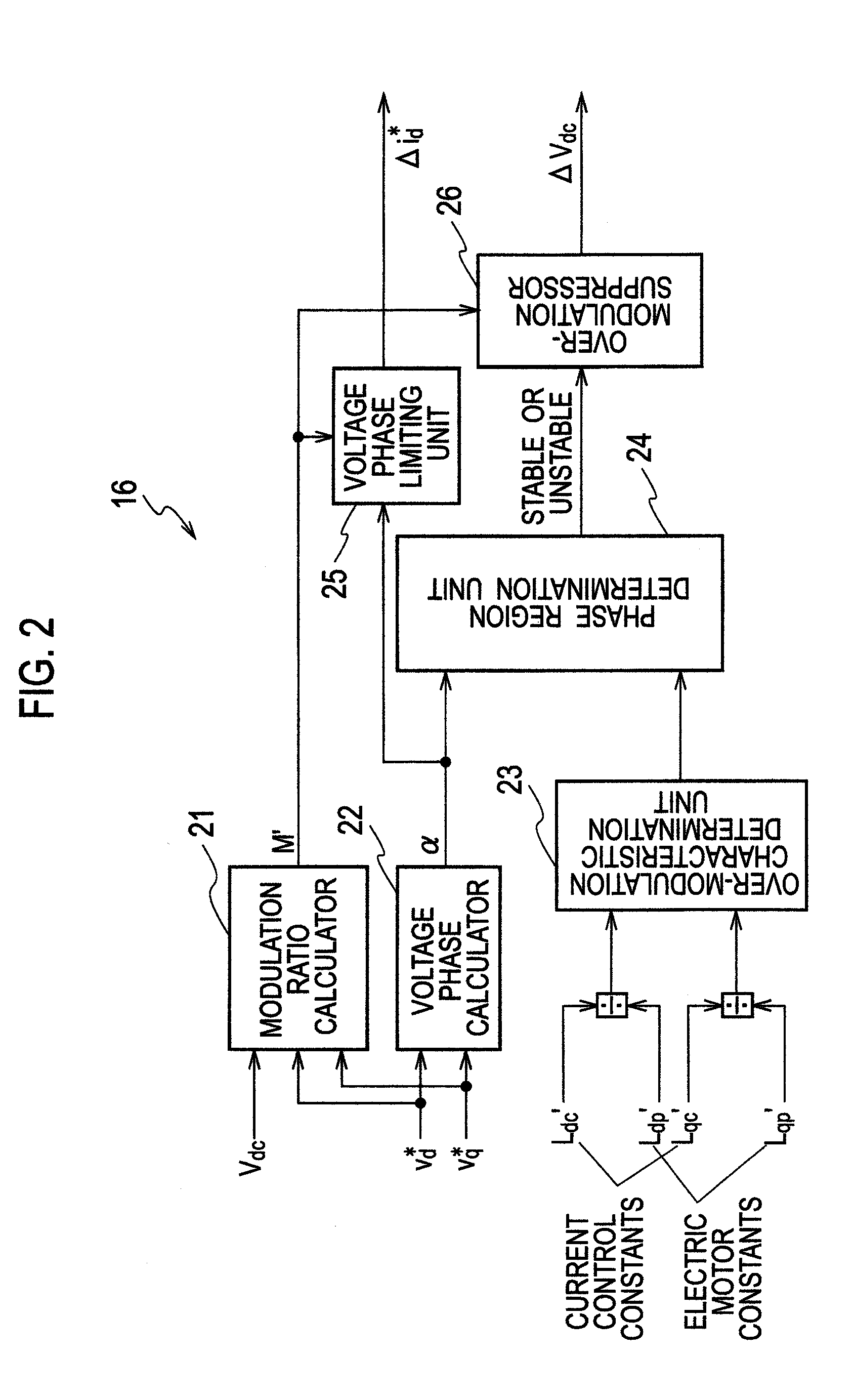
[0099]Although the over-modulation processing unit 16 of the first embodiment shown in FIG. 1 receives the current control constants and the electric motor constants, the over-modulation processing unit 76 of the embodiment receives...

third embodiment

[0120]Next, the third embodiment to which the present invention is applied is described with reference to the drawings. The same parts as those in the first and second embodiments described above are denoted by the same reference numerals and detailed description thereof is omitted.

[0121][Overall Configuration of Control Device for Electric Motor]

[0122]FIG. 11 is a block diagram showing a configuration of a control device for an electric motor in the embodiment. As shown in FIG. 11, a control device 111 for the electric motor in the embodiment includes the same constitutional elements as those in the control device 1 for the electric motor in the first embodiment which are shown in FIG. 1, but is different in inputs and outputs of an over-modulation processing unit 116. The over-modulation processing unit 116 of the embodiment receives only voltage command values vd*, vq* and outputs current control constants Ldc′, Lqc′ as outputs.

[0123][Configuration of Over-Modulation Processing U...


PUM


Abstract

A control device 1 for an electric motor of the present invention includes: a current control unit 4 configured to calculate voltage command values vd*, vq* used to drive an electric motor 100, on the basis of a state quantity for voltage command value calculation and q and d-axis current detection values id, iq, the state quantity calculated from a torque command value T*; and an over-modulation processing unit 16 configured to determine whether the electric motor 100 is stable or unstable in an over-modulation state, on the basis of the voltage command values vd*, vq*, current control constants, and electric motor constants, and to drive the electric motor 100 in the over-modulation state when determining that the electric motor 100 is stable.

Description

TECHNICAL FIELD[0001]The present invention relates to a control device for an electric motor and a control method for an electric motor which control an electric motor by performing vector control, and particularly relates to a control device for an electric motor and a control method for an electric motor which drive an electric motor by determining whether the electric motor is stable or unstable in an over-modulation state.BACKGROUND ART[0002]Conventionally, in an AC electric motor, so-called current vector control has been performed in which current feedback control is performed on d and q axes. Patent Literature 1 discloses an example of a drive control device for an AC electric motor which performs such current vector control.[0003]In the conventional drive control device for an AC electric motor disclosed in Patent Literature 1, different types of control are performed in a normal modulation region in which a pseudo sine wave voltage can be achieved by pulse width modulation ...

Claims


Application Information

Patent Timeline
IPC IPC(8): H02P21/05H02P21/22H02P21/00H02P27/04H02P27/08
CPCH02P21/14H02P21/145H02P21/05H02P21/0035H02P21/06H02P21/0085H02P21/0089H02P21/16H02P21/22
Inventor SHOJI, MITSUHIRONAKAMURA, HIDEO
Owner NISSAN MOTOR CO LTD
Why Eureka
Try Eureka