Minimal incision removable bone screw, driver, and method of use

a bone screw and mini-incision technology, applied in the field of bone screw driver, can solve the problems of rheumatic or osteoarthritic flare-up, inability to fully understand the long-term deleterious effects of a metal such as stainless steel or titanium alloy implanted in the body, and the removal of the metal requires considerable effort and risk, and achieves the effect of convenient placement and easy removal

Active Publication Date: 2014-02-13
HORWITZ MICHAEL H
View PDF9 Cites 8 Cited by
  • Summary
  • Abstract
  • Description
  • Claims
  • Application Information

AI Technical Summary

Benefits of technology

[0026]The tissue over the insertion site is then closed. When soft tissue closure over the screw involves capsule and / or subcutaneous layers, the capsule and layers can be closed over the screw head, a small incision made, and the layers pushed down below the head and over the compression member before closing the epidermis. On removal of the screw, only the epidermis needs to be incised to expose the screw head for removal of the screw. In most cases, further incision of the subcutaneous layers is not needed. This ease of removal is a major advantage of the present invention.
[0027]Previously, those concerned with internal fixation bone screws have believed that minimizing the protrusion of the head from the surface of the bone to which it is affixed is of great importance. See for example Zang, U.S. Pat. No. 5,556,225. In accordance with the present invention, accessibility of the head and ease of removing an internal fixation screw have been found to be more important. An additional advantage to having removable hardware that is easy to remove is that it is equally easy to replace. This means that should a screw lose purchase, a larger screw can serve as a replacement screw without the necessity of removal through a large incision and reevaluation of the exact size.
[0028]After the bone fracture has healed sufficiently, in accordance with radiographic and clinical evidence (frequently two to eight weeks after the procedure), the head of the screw is located either by palpation or by other means such as needle or fluoroscopy, and a small incision is made to expose the screw head.
[0029]Particularly if the screw head is near the surface, a small stab incision may be sufficient to access the screw head. The head of the screw may be cleaned, although this step is far less important than with a screw head relying on a depression in the top of the head for engagement with the driver. The screwdriver is placed over the head. Because the head is separate from the compression member, it is easily reached, and because the head is undercut, tilting the screwdriver allows it to exert a gentle outward force on the screw. The screwdriver is used for turning and removing the screw from the bone. The rounded shape of the head allows positive contact between the side walls of the driver socket and the head throughout a range of angles of at least fifteen degrees. Therefore, the driver may be tilted a few degrees from the axis of the screw, preferably around ten to twenty degrees, and used for gently lifting the screw.
[0030]When the screw is clear of the bone, it may be removed with forceps. The small incision is closed, preferably after bathing it. The bone is then allowed to regrow into the cavity left by the screw. It will be seen that the screw head will frequently be so close to the epidermis and will be so completely exposed by even a small incision, that removal of the screw may not even be dependent on the special qualities of the screwdriver.
[0031]The screw, driver, and methods of the present invention are particularly well suited to surgery on the human foot and hand. Examples are fractures of the phalanges, metatarsals, or talus of the foot, fractures of the phalanges or scaphoid of the hand, and in osteotomies of the hand and foot such as bunion repair through a modified Scarf / Akin osteotomy or a repair of a Jones fracture of the hand. It will be understood that osteotomies may involve both the removal of bone and the insertion of bone between bone fragments, so that the screw may pass through more than one proximal bone fragment. It will also be understood that the screw, driver, and methods of the invention are applicable to a wide range of other procedures on human and non-human vertebrate bones, including for example, other osteotomies and fractures of the hip, leg, arm, spine, or clavicle. The screw, driver and methods may also be useable with non-metallic, biocompatible, and bioabsorbable plating devices to avoid long-term exposure to metal components.

Problems solved by technology

Furthermore, the long-term deleterious effects of a metal such as stainless steel or a titanium alloy implanted in the body are not fully understood.
It is not uncommon for barometric pressure and changes in ambient temperature to cause rheumatic or osteoarthritic flare-ups.
Such removal, however, requires considerable effort and risk, as suggested by patents such as Bonati et al., U.S. Pat. No. 7,090,680, Steffee, U.S. Pat. No. 4,854,311, Vasta et al., U.S. Pat. No. 7,582,093, or Lindemann et al., U.S. published application US 2007 / 0270880 A1.
When faced with having to remove a screw of the prior art, a surgeon must deal with creeping fibrosis, meaning soft tissues that creep into the screw threads making it difficult to access the screw without an incision into periosteal structures and more trauma.
This usually requires cutting the screw or severe countersinking.
These screws, however, are not as strong as metal screws, require drilling and tapping with metal instruments, and are transparent to x-rays.
Hybrid metal and polymer screws are disclosed in Fischer et al., U.S. Pat. No. 4,711,232 and in TenHuisen et al., U.S. Pat. No. 6,916,321, but these screws add complexity and do not solve all of the problems with leaving metal in the body.
This approach is costly and has not been entirely satisfactory.

Method used


Image

  • Minimal incision removable bone screw, driver, and method of use
  • Minimal incision removable bone screw, driver, and method of use
  • Minimal incision removable bone screw, driver, and method of use

Examples


Embodiment Construction

[0055]The following detailed description illustrates the invention by way of example and not by way of limitation. The description clearly enables one skilled in the art to make and use the invention, describes several embodiments, adaptations, variations, alternatives, and uses of the invention, including what is presently believed to be the best mode of carrying out the invention.

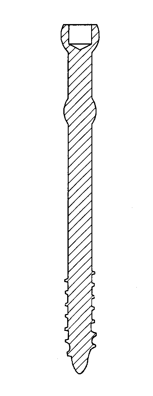
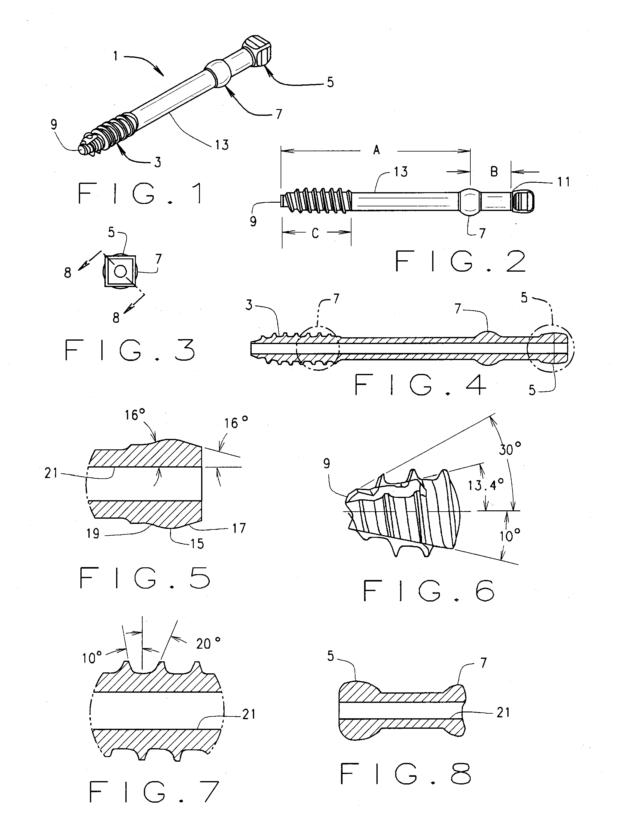
[0056]As shown in FIGS. 1-8, in accordance with one embodiment, a bone screw 1 comprises a thread 3 at its distal end, a head 5 at its proximal end, and a bone-engaging compression member 7 spaced distally from the head. The screw 1 may be made of any biocompatible material, but is preferably made of stainless steel, titanium, or titanium alloy. In this illustrative embodiment, it is made of the titanium alloy known as Ti6Al4V ELI, with an anodized finish in accordance with SAE AMS2488D.

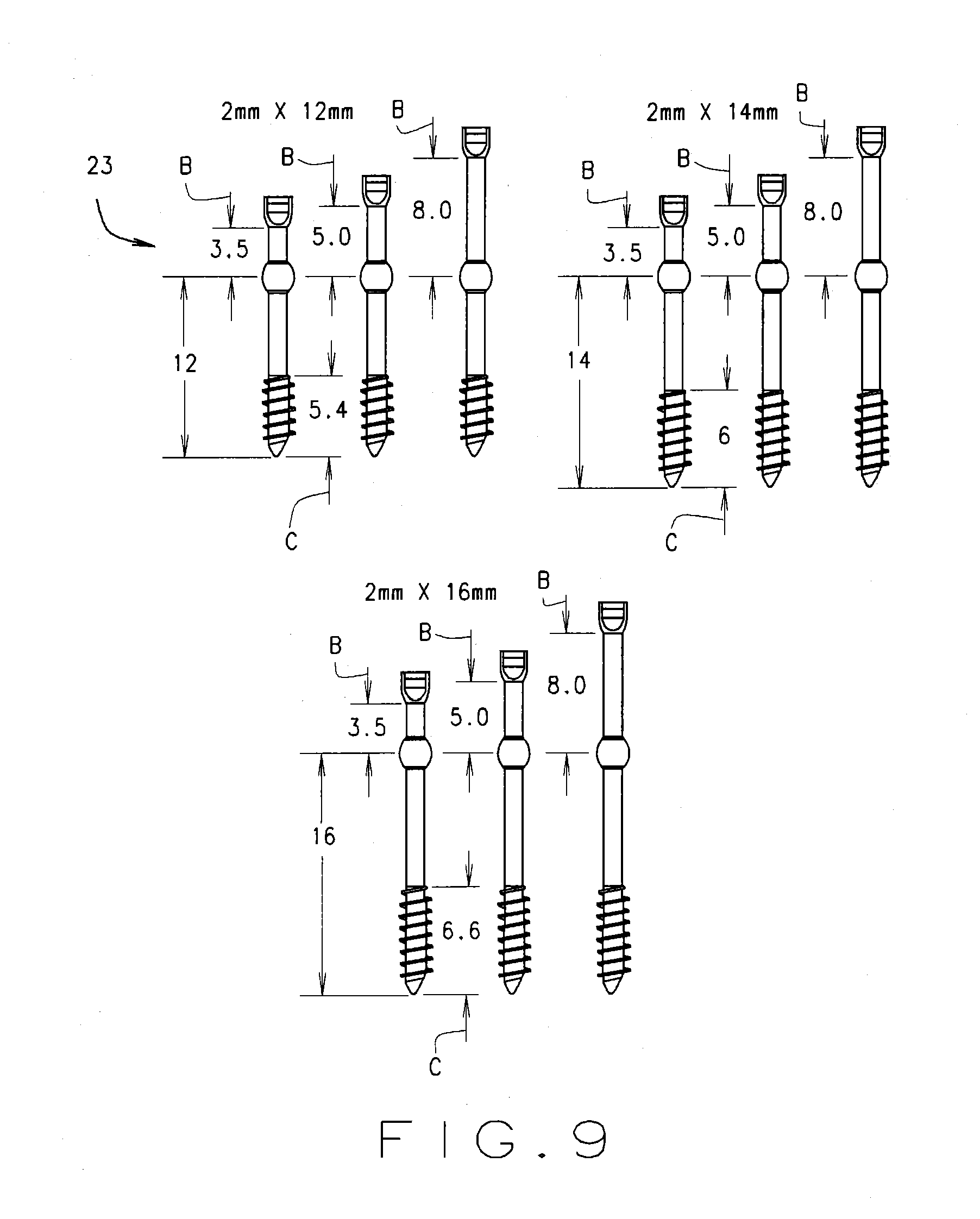
[0057]The screw 1 is first identified by its diameter and by its length, as in a standard lag bone screw. Diameter is de...


PUM


Abstract

A surgical bone screw (1) and driver (31), and a method for using them for repairing an osteotomy or fracture. The screw has a shaft having a head (5) at its proximal end, screw threads (3) at its distal end and a compression member (7) between the head and the screw threads. In an embodiment, the threads are self-tapping and self-drilling, the head is polygonal, and the sides of the polygon are convex. The driver turns the screw until the threads cross a fracture site and the compression member contacts the proximal bone fragment. The threads and compression member draw the fragments together and leaves the head entirely clear of the bone surface. The screw is removed through a small incision. Tilting the driver to allow the socket to engage an inwardly extending lower portion of the head permits the driver to lift the screw out of the bone.

Description

CROSS-REFERENCE TO RELATED APPLICATIONS[0001]This application is a continuation of International Application No. PCT / US2012 / 047743, filed Jul. 20, 2012, which is related to, and claims priority from U.S. provisional applications Ser. No. 61 / 509,940, filed 20 Jul. 2011, and Ser. No. 61 / 673,681 filed 19 Jul. 2012, the disclosures of which are hereby incorporated by reference.STATEMENT REGARDING FEDERALLY SPONSORED RESEARCH[0002]Not Applicable.TECHNICAL FIELD[0003]The present invention relates to a bone screw, a driver for the screw, and a method of applying and removing the screw. The system may be used as a removable fixation system for any osteotomy or fracture requiring lag compression. The screw has particular application for interfragmentary internal fixation of small bones, such as those of the foot, hand, and ankle, but is also useful with osteotomies or fractures of large bones and spine.BACKGROUND ART[0004]When a bone is fractured, either by deliberately cutting it (osteotomy...

Claims


Application Information

Patent Timeline
Patent Type & Authority Applications(United States)
IPC IPC(8): A61B17/86
CPCA61B17/864A61B17/863A61B17/862A61B17/8625A61B17/8875A61B17/8883F04C2270/0421A61B2017/8655
Inventor HORWITZ, MICHAEL H.
Owner HORWITZ MICHAEL H
Why Eureka
Try Eureka