
Offset-induced signal cancellation in an interleaved sampling system

a sampling system and signal cancellation technology, applied in pulse manipulation, pulse technique, instruments, etc., can solve problems such as solving a very low level signal

Active Publication Date: 2014-02-20
AVAGO TECH INT SALES PTE LTD
View PDF2 Cites 1 Cited by
  • Summary
  • Abstract
  • Description
  • Claims
  • Application Information

AI Technical Summary

Benefits of technology

This patent describes a device called an interleaved sampled controller that can sample and hold input signals. It uses multiple sample and hold circuits, and a single multiplexer to connect them to an output. This device can sample at a high rate and has a unique way of interleaving the sample and hold circuits. One technical effect of this invention is that it allows for efficient and accurate sampling of input signals.

Problems solved by technology

For some of these sensitive measurements, however, it is necessary to resolve a very low level signal in the presence of noise and other large signal interferers.

Method used


Image

  • Offset-induced signal cancellation in an interleaved sampling system
  • Offset-induced signal cancellation in an interleaved sampling system
  • Offset-induced signal cancellation in an interleaved sampling system

Examples


Embodiment Construction

[0018]Reference herein to “one embodiment” or “an embodiment” means that a particular feature, structure, or characteristic described in connection with the embodiment can be included in at least one embodiment of the invention. The appearances of the phrase “in one embodiment” in various places in the specification are not necessarily all referring to the same embodiment, nor are separate or alternative embodiments necessarily mutually exclusive of other embodiments. The same applies to the term “implementation”.

[0019]It should be understood that the steps of the exemplary methods set forth herein are not necessarily required to be performed in the order described, and the order of the steps of such methods should be understood to be merely exemplary. Likewise, additional steps might be included in such methods, and certain steps might be omitted or combined, in methods consistent with various embodiments of the present invention.

[0020]Also for purposes of this description, the ter...


PUM

PropertyMeasurementUnit
timeaaaaaaaaaa
frequencyaaaaaaaaaa
timeaaaaaaaaaa

Abstract

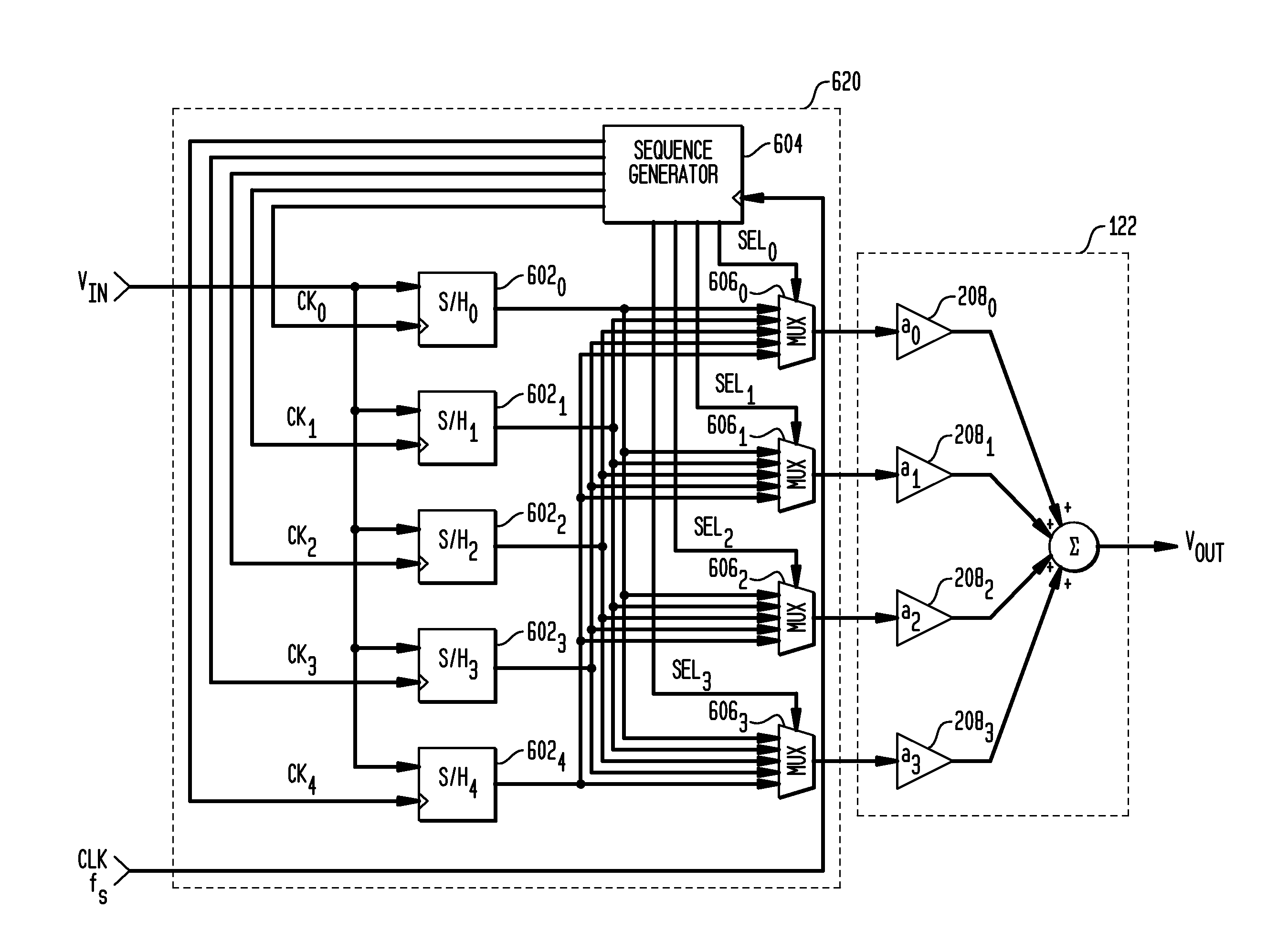
Described embodiments provide an interleaved sampler having N sample and hold circuits for sampling an input signal, and M multiplexers. Each multiplexer is adapted to couple all N of the plurality of sample and hold circuits to a respective output of the interleaved sampler. The interleaved sampler samples at a sample rate of fs, has an interleaved sampling period of M / fs, where M is greater than one and less than N. Because there are more sample and hold circuits than there are samples taken during an interleaved sampling period, different combinations of the sample and hold circuits are used from interleaved sample period to interleaved sample period. This reduces spurious tones generated from offset voltages when using interleaved sample and hold circuits. The order of the sample and hold circuits are clocked might be random, pseudorandom, or a fixed pattern longer than the interleaved sampling period.

Description

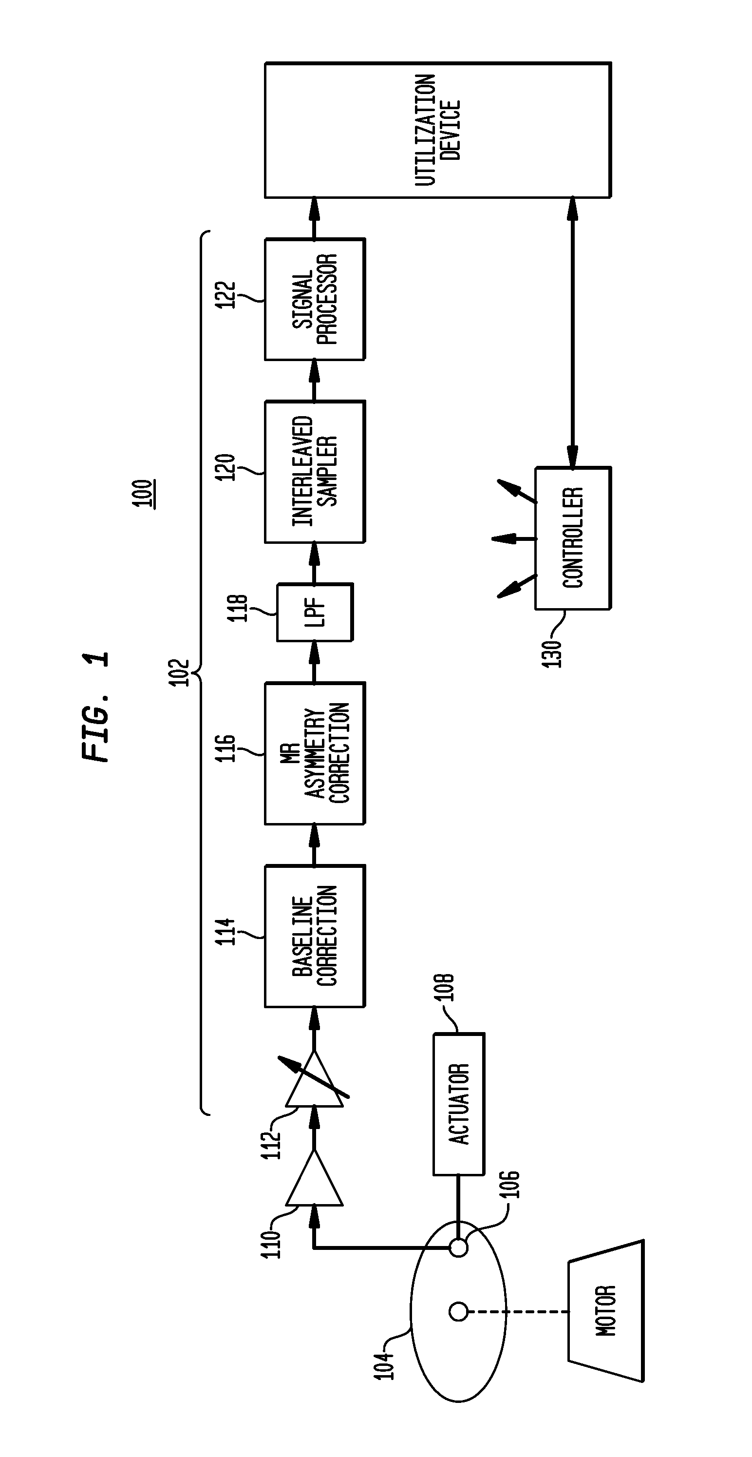
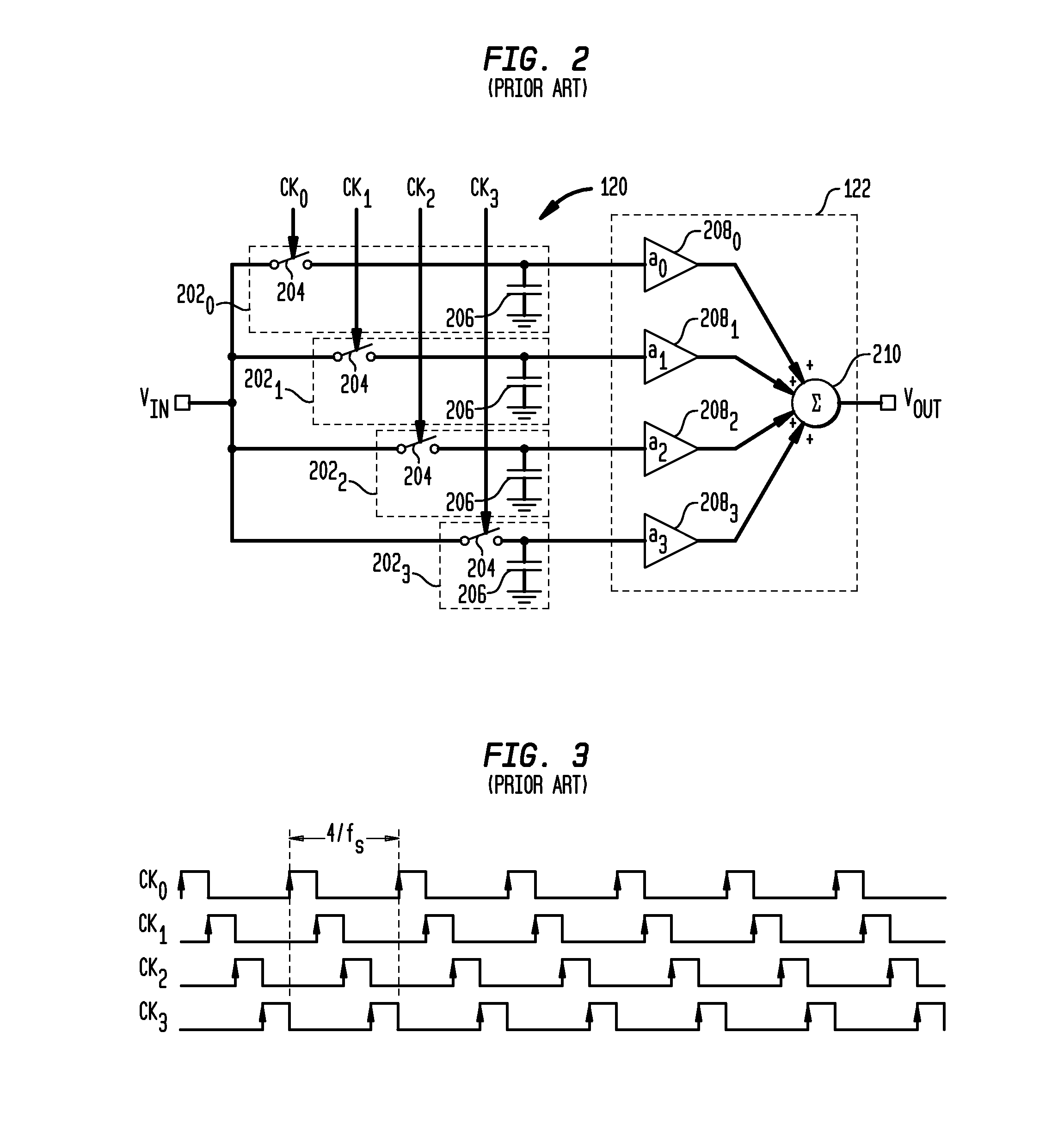
BACKGROUND OF THE INVENTION[0001]In hard-drive systems, the data is stored as magnetic flux regions or “magnets” along the surface of a rapidly spinning magnetic media or hard disk with one or more read / write heads “floating” or “flying” very near the media surface. Given the high data rates and low latency requirements of modern hard-drive read channels, data read from the hard disk is sampled using interleaved sampling techniques. The sampled data is converted by a quantizer, forming an interleaved analog-to-digital converter (ADC) and then processed digitally, or the sampled data is processed with sampled analog techniques, or a combination of both.[0002]Controlling the position of the head along the media uses a repeating pattern of magnets. Unlike data that has a somewhat random pattern, repeating patterns (e.g., 2 T magnet length having a pattern . . . 11001100 . . . ) is readily detectable and produces “tones” or signals having a frequency corresponding to the magnet rate and...

Claims


Application Information

Patent Timeline
Patent Type & Authority Applications(United States)
IPC IPC(8): H03K5/00G11B27/10
CPCG11C27/02H03M1/1215H03M1/1245
Inventor GREENE, ROBERT ALAN
Owner AVAGO TECH INT SALES PTE LTD
Learn More