System and method for MRI imaging using polarized light

Inactive Publication Date: 2014-02-20
ASPECT IMAGING
View PDF6 Cites 51 Cited by
  • Summary
  • Abstract
  • Description
  • Claims
  • Application Information

AI Technical Summary

Benefits of technology

[0008]It is an object of the present invention to disclose a system and method for MRI imaging the body

Problems solved by technology

Both low SNR and low contrast can make it difficult to understand MRI images.
There is a further disadvantage in that systems with high magnetic field can damage animal, so that very high magnetic fields ar

Method used


Image

  • System and method for MRI imaging using polarized light
  • System and method for MRI imaging using polarized light
  • System and method for MRI imaging using polarized light

Examples


Embodiment Construction

[0037]The following description is provided, alongside all chapters of the present invention, so as to enable any person skilled in the art to make use of said invention and sets forth the best modes contemplated by the inventor of carrying out this invention. Various modifications, however, will remain apparent to those skilled in the art, since the generic principles of the present invention have been defined specifically to provide a means and method for providing functional MRI with high signal to noise ratio and high contrast.

[0038]In conventional MRI systems, systems with high magnetic field (from 3 Tesla, e.g., approximately 13T) provide images with high SNR but low contrast. Systems with low magnetic field (less than 3 Tesla, e.g., approximately 1T) provide images with much lower SNR but higher contrast. Both low SNR and low contrast can make it difficult to understand MRI images.

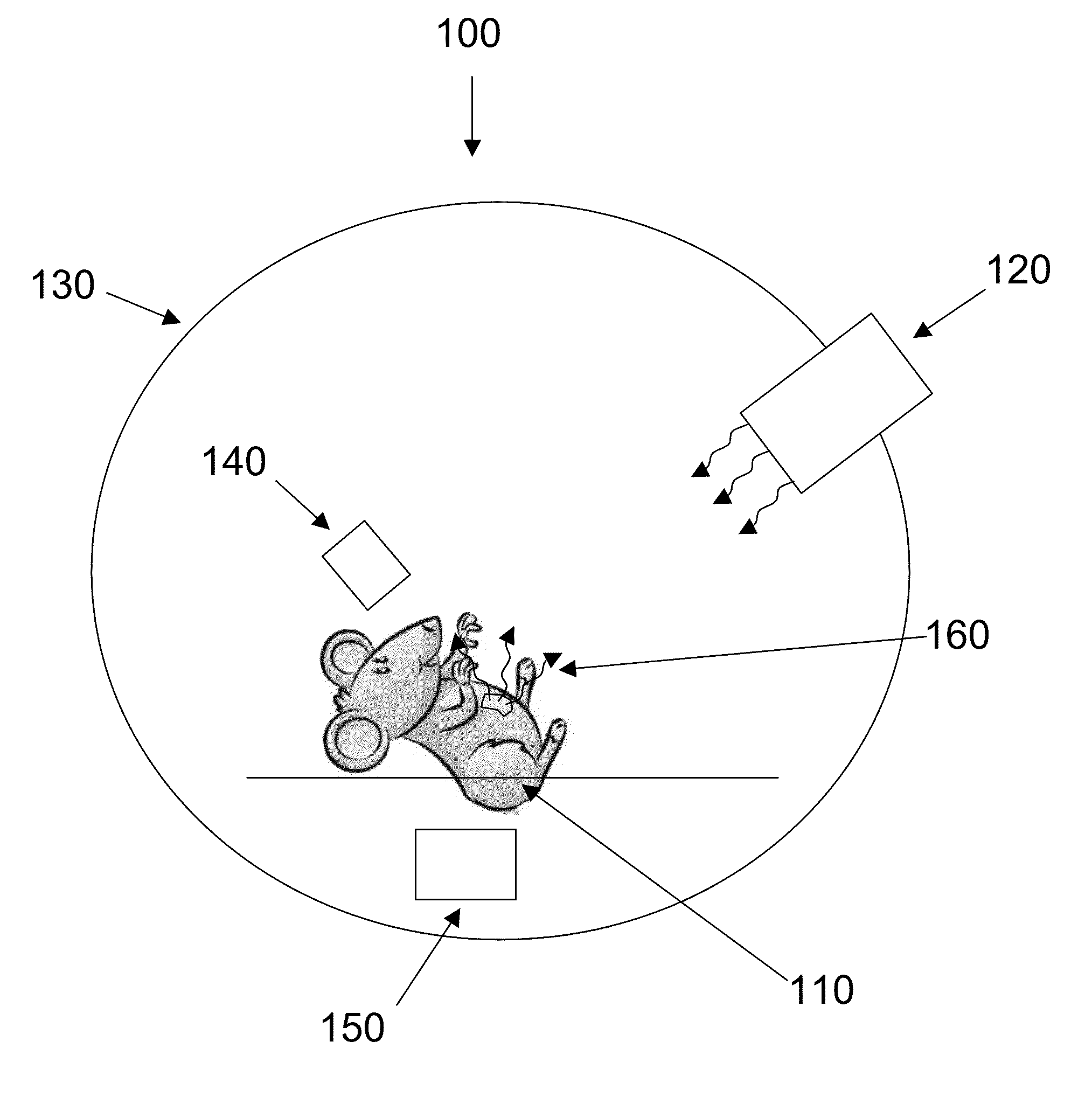
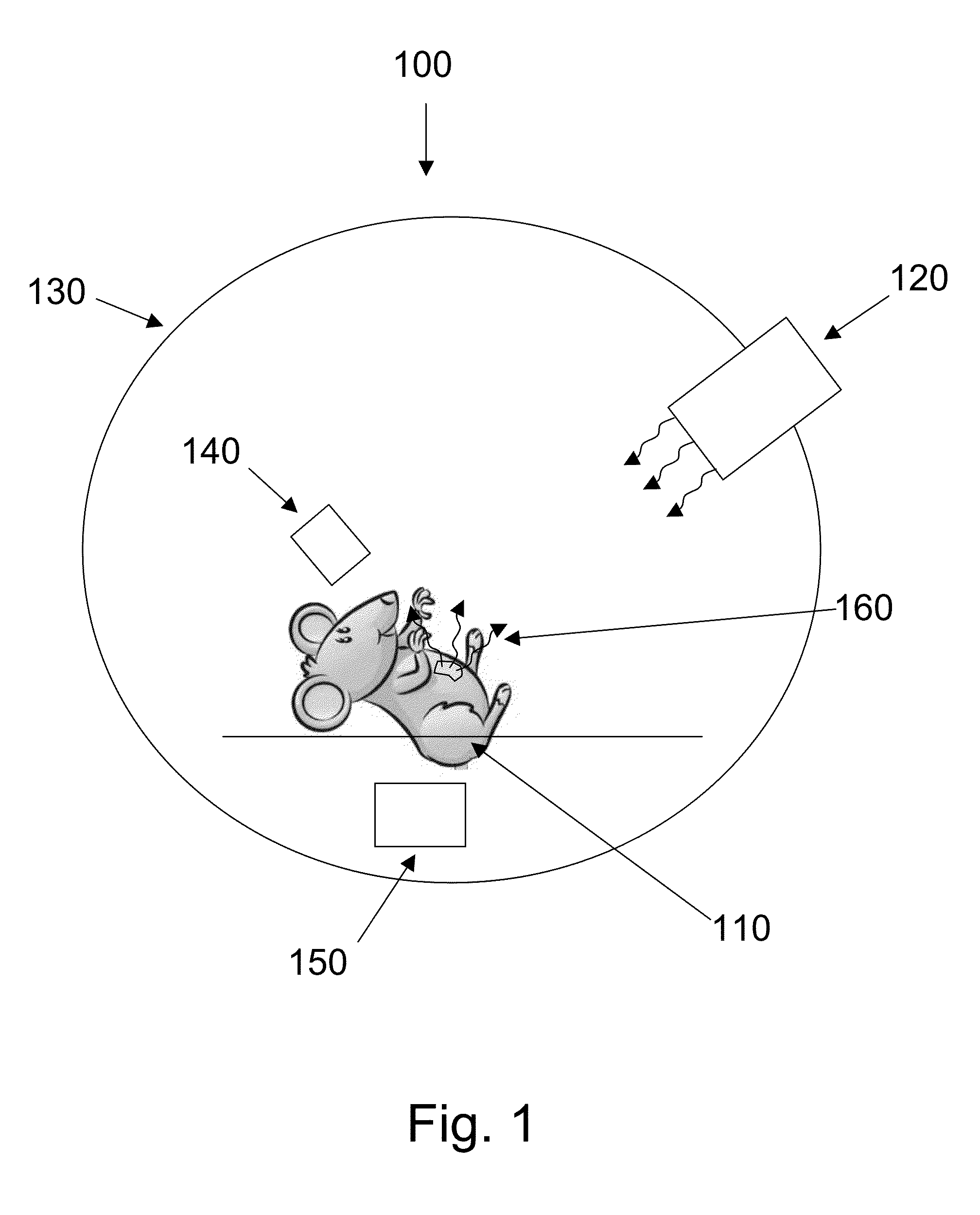
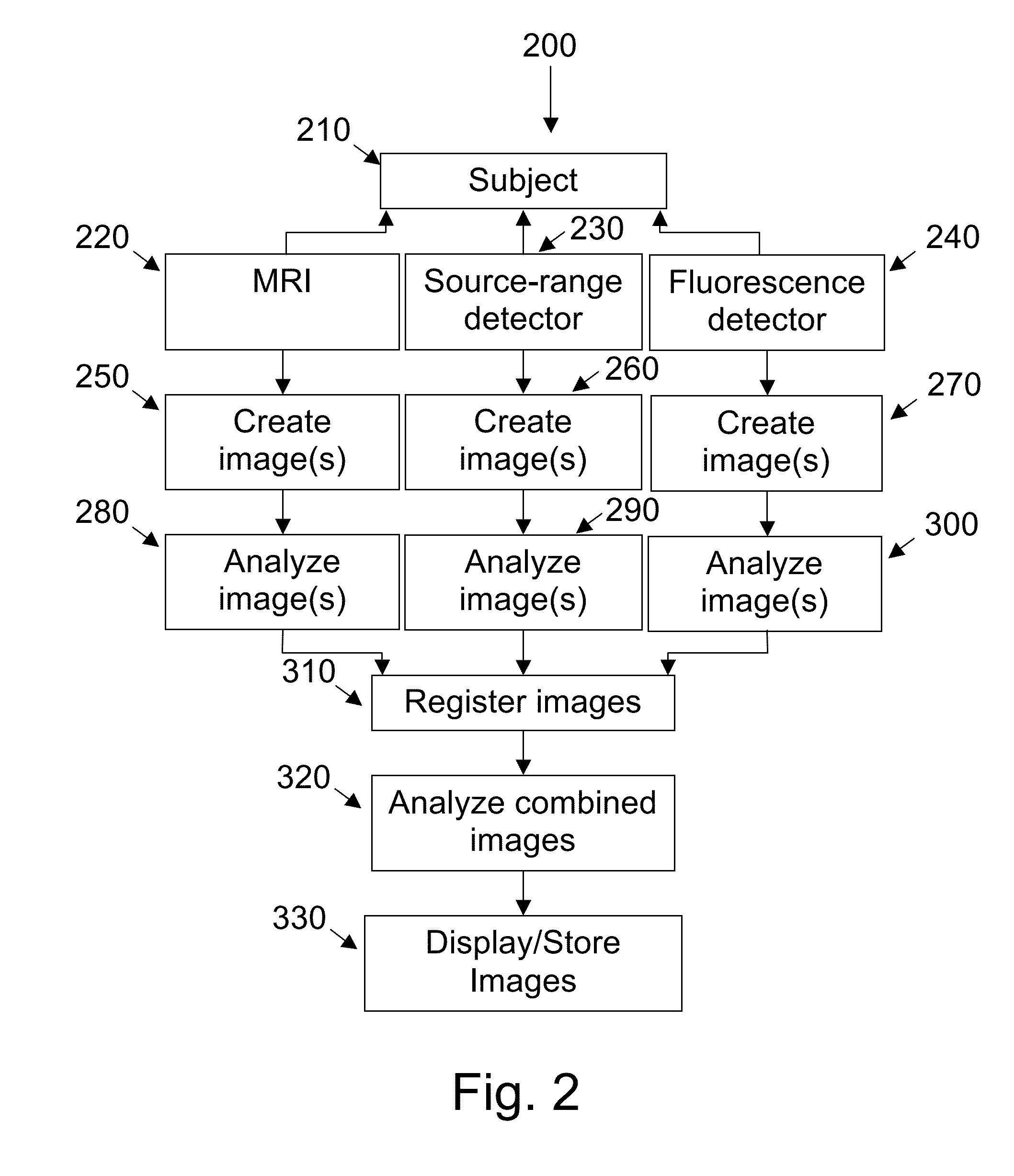
[0039]The system of the present invention combines a low-field (1 T) MRI image with camera image...


PUM


Abstract

A magnetic resonance imaging (MRI) imaging system, including: an MRI device adapted to image at least a portion of an animal; a photon source; an imaging photon detector that detects photons emitted by the photon source; and an image processor that superimposes the MRI image and the photon detector image. The system also includes one or more polarizers located between the animal and the photon detector.

Description

FIELD OF THE INVENTION[0001]The present invention generally pertains to a system and method for MRI imaging the body of an animal using polarized light to provide images with high signal to noise ratio and high contrast.BACKGROUND OF THE INVENTION[0002]In conventional MRI systems, systems with high magnetic field (approximately 13T) provide images with high signal to noise ratio (SNR) but low contrast. Systems with low magnetic field (approximately 1T) provide images with much lower SNR but higher contrast. Both low SNR and low contrast can make it difficult to understand MRI images.[0003]There is a further disadvantage in that systems with high magnetic field can damage animal, so that very high magnetic fields are better avoided.[0004]Patent application US 20110073764A1 discloses a method and system for nuclear imaging normally involve detection of energy by producing at most two or three bursts of photons at a time in response to events including incident gamma radiation. F numbe...

Claims


Application Information

Patent Timeline
IPC IPC(8): G01R33/48
CPCG01R33/4808A61B6/5247A61B8/5261A61B5/0059A61B5/0071A61B5/055A61B5/0035A61B5/7425
Inventor RAPOPORT, URIBATT, ARYEH
Owner ASPECT IMAGING
Why Eureka
Try Eureka