Apparatus and method for monitoring a card slot
- Summary
- Abstract
- Description
- Claims
- Application Information
AI Technical Summary
Benefits of technology
Problems solved by technology
Method used
Image

Examples
Embodiment Construction
[0030]Although embodiments of the invention will be described below with reference to automated teller machines, ATMs (which are also known as automated banking machines), and the card readers used therein, it will be appreciated that the invention can be applied to any terminal or device into which a user can insert a bank or payment card through a slot. Furthermore, although the card readers described below are motorised card readers which draw the inserted card further into the machine to read the information stored on the card, the invention can be used with other types of card readers, for example dip card readers, in which the user places the card in the required position.
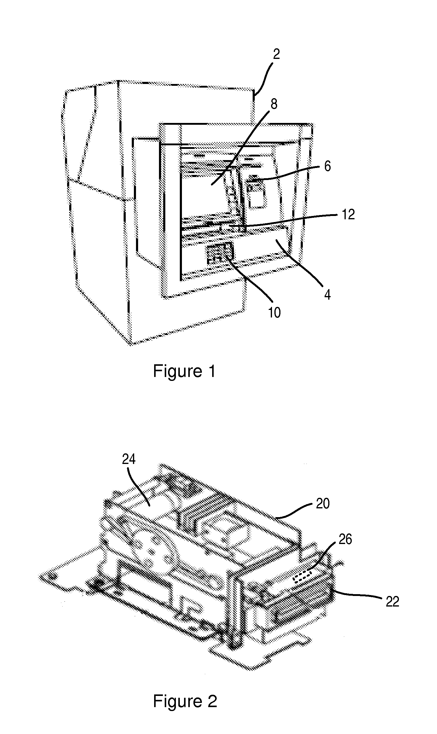
[0031]FIG. 1 is an illustration of a conventional automated teller machine, ATM. The ATM 2 comprises a fascia 4 having an external card slot 6 into which a user can insert their card, a display 8 for presenting information and / or options to a user, a keypad 10 for allowing a user to input their PIN and select...
PUM
 Abstract
Description
Claims
Application Information