Mr imaging guided therapy system

a guided therapy and imaging technology, applied in the field of magnetic resonance imaging, can solve the problems of limiting the design of optimized rf electromagnetic field, affecting the efficiency of treatment tissue, so as to achieve high power efficiency, avoid overheating of treated tissue, and not dissipate power

Inactive Publication Date: 2014-02-27
KONINKLIJKE PHILIPS ELECTRONICS NV
View PDF13 Cites 7 Cited by
  • Summary
  • Abstract
  • Description
  • Claims
  • Application Information

AI Technical Summary

Benefits of technology

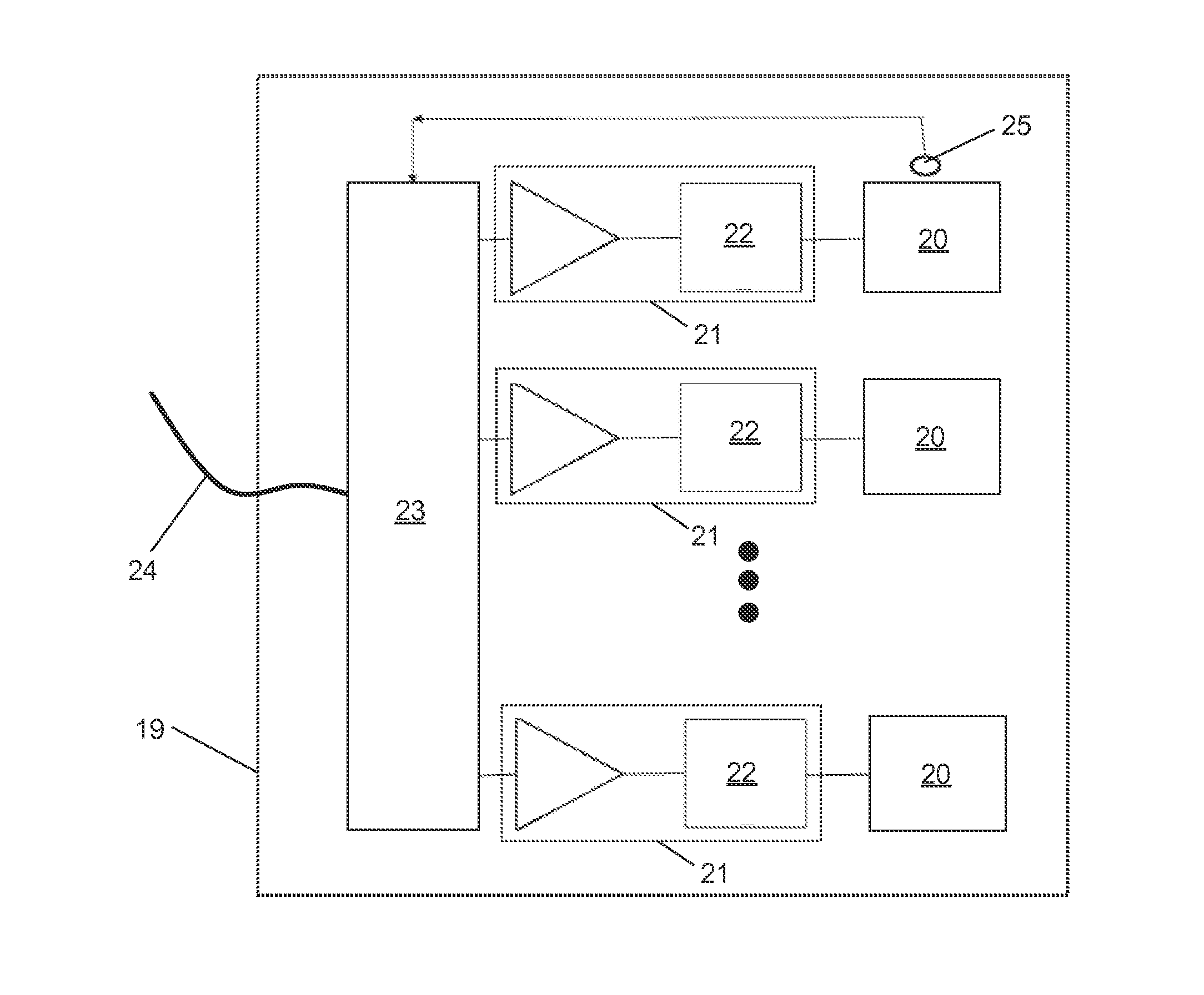
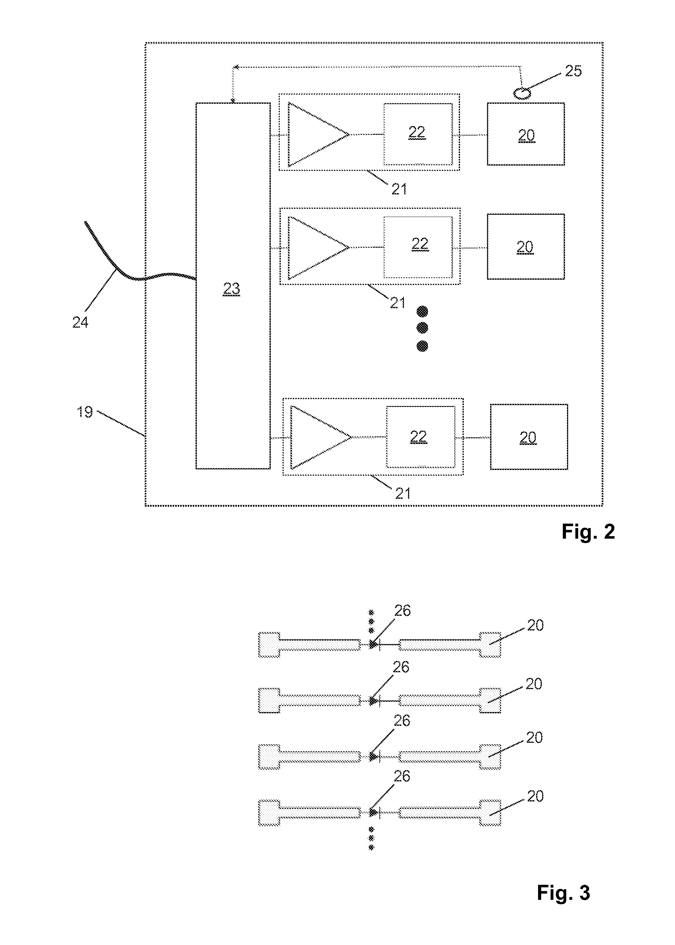
[0015]The thermal treatment applicator of the invention comprises a plurality of RF antennae and a plurality of RF power amplifiers supplying RF signals to the RF antennae, wherein the RF power amplifiers are preferably associated with the RF antennae on a one-to-one basis. It is the gist of the invention to make provision for an output matching network in each RF power amplifier which transforms the output impedance of the transistor (e.g. a high power MOSFET) into a low impedance value. In this way the inter-antenna isolation within the array of RF antennae is improved. In particular for each RF amplifier there is provided its repective output matching network. Each RF power amplifier has its output coupled to its output matching network and said output network supplies the RF signal from the RF power amplifier to the RF antenna that is energised by the RF signal. Thus, the treatment applicator is provided with a multi-channel power supply, where each channel includes an RF amplifier and an output matching network and an RF antenna. In each channel, the RF amplifier in that channel supplies the RF signal via the output matching network of that channel to the RF antenna of that channel. Each channel has its proper output matching network circuited between its RF amplifier and its RF antenna. Further and each RF power amplifier is connected directly to the RF antenna via the output network associated with the respective RF power amplifier. That is the output network is directly connected to its associated RF antenna. Thus, the thermal treatment applicator of the invention has the RF antennae and its associated RF power amplifiers integrated with the output matching network in an integrated module.
[0018]RF antenna to the optimum load of the transistor (typically 50 Ω) of the respective RF power amplifier for maximizing the available output power. The approach of the invention benefits from a distinctive current-source characteristic of the RF power amplifiers, thereby exhibiting a superior robustness against load variations which is a further important advantage.
[0021]According to a preferred embodiment of the invention, each RF power amplifier is connected directly to the RF antenna associated with the respective RF power amplifier. A direct connection means that the RF power amplifiers are actually located “on” the applicator, i.e. the RF antennae as well as the RF power amplifiers are integral components of a unit constituting the thermal treatment applicator of the invention. It is essential that the RF amplifiers are located near the RF antennae, whereby inter-antenna coupling is further reduced. Moreover, the required RF power can be reduced because lossy cable connections between the RF power amplifiers and the associated RF antennae are avoided. In any case, the length of the connection between the RF power amplifiers and the respective RF antennae should be significantly less than half the wavelength of the RF signals at the RF operation frequency of the applicator.
[0023]According to another preferred embodiment of the invention, the thermal treatment applicator further comprises RF traps connected to the RF antennae, which RF traps are tuned to the MR resonance frequency of a MR device which is used in combination with the applicator. In this way, the absorption of RF energy radiated by the MR device for excitation and / or manipulation of magnetic resonance in the applicator is minimized. Furthermore, the RF antenna preferably comprises PIN diode switches. In this way, the RF antennae of the applicator are made transparent to the RF field generated by the MR device. PIN diode switches should be used in the RF antennae of the applicator in case the MR resonance frequency of the MR device is close to the RF operation frequency of the applicator.
[0025]The applicator may further comprise a feedback loop formed by a pick-up antenna for picking up electromagnetic radiation from a target zone irradiated by the RF antennae, which pick-up antenna is connected to the controllable signal generator. The pick-up antenna works as a sensor element which detects the amplitude of the RF electromagnetic field generated within the target zone. In this way, overheating of the treated tissue can be avoided and load variations can be compensated for automatically.
[0036]The thermal treatment applicator according to the invention can advantageously be used in combination with most MR imaging devices presently being used in clinical practice, wherein the thermal treatment applicator may be located within the examination volume of the MR device. The interconnection of the thermal treatment applicator and the back-end electronics of the MR device can be established, for example, via an optical link. Preferably, the thermal treatment applicator operates at a RF frequency which is different from the MR resonance frequency. In this way, interferences between the operation of the thermal treatment applicator and the MR examination are avoided.

Problems solved by technology

As the temperature rises above 55° C., coagulative necrosis of the tissue occurs resulting in cell death.
In conventional thermal treatment applicators the mutual coupling of the individual RF antennae is a limiting factor for the design of optimized RF electromagnetic field characteristics.
Further disadvantages of known applicator designs are significant RF power loss in feeding cables, via which the RF energy is supplied from the RF power amplifiers to the RF antennae, as well as the use of inefficient RF power amplifiers.
Power efficiency of the RF power amplifiers results not only in wasted power but also in a large heat production.
The heat load on the RF electronics makes the design more expensive and bulky, because provision has to be made for an appropriate cooling system, and / or negatively impacts reliability of the system.

Method used


Image

  • Mr imaging guided therapy  system
  • Mr imaging guided therapy  system
  • Mr imaging guided therapy  system

Examples


Embodiment Construction

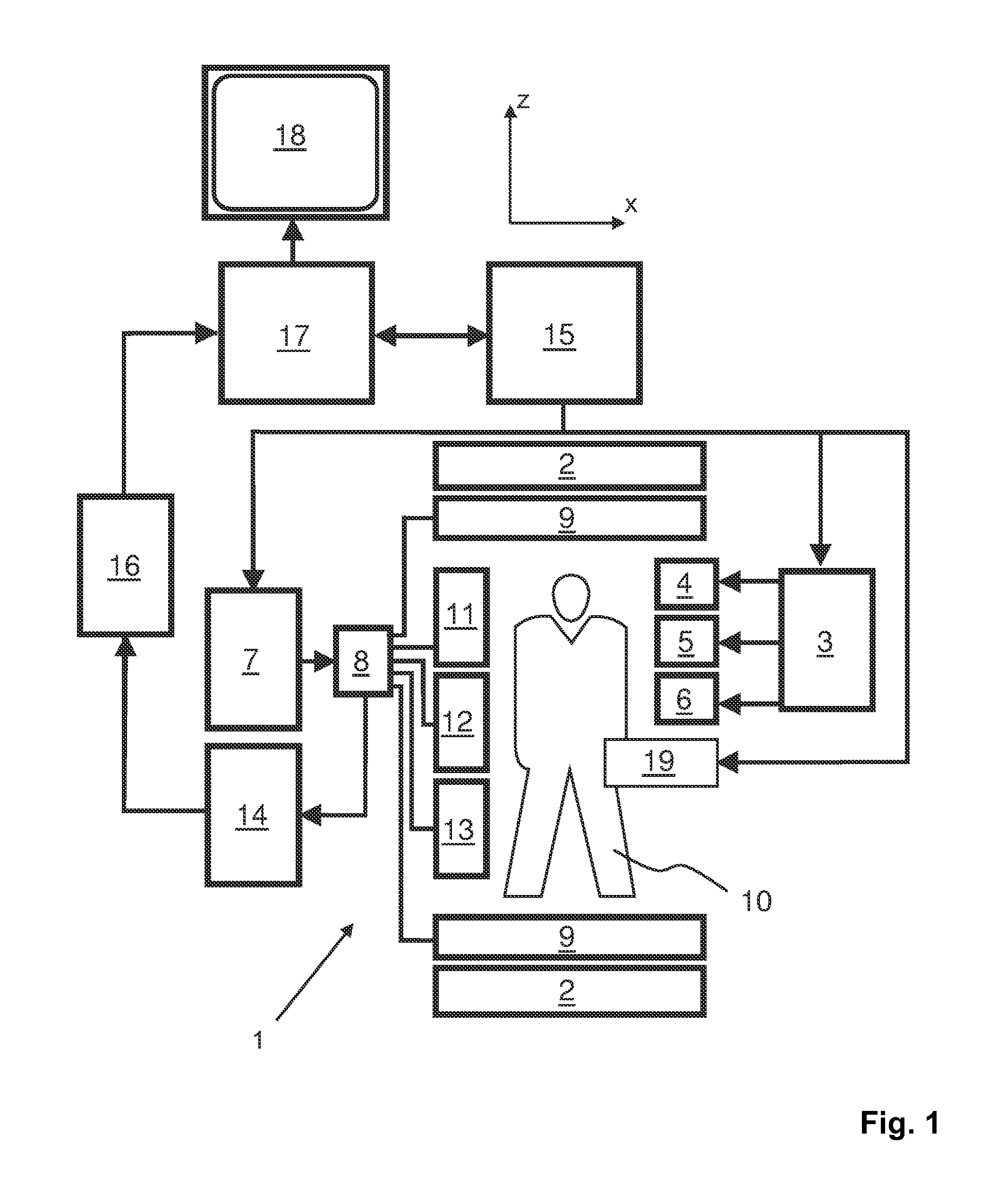
[0041]With reference to FIG. 1, a MR imaging guided therapy system 1 is shown. The system comprises superconducting or resistive main magnet coils 2 such that a substantially uniform, temporally constant main magnetic field is created along a z-axis through an examination volume.

[0042]A magnetic resonance generation and manipulation system applies a series of RF pulses and switched magnetic field gradients to invert or excite nuclear magnetic spins, induce magnetic resonance, refocus magnetic resonance, manipulate magnetic resonance, spatially and otherwise encode the magnetic resonance, saturate spins, and the like to perform MR imaging.

[0043]More specifically, a gradient pulse amplifier 3 applies current pulses to selected ones of whole-body gradient coils 4, 5 and 6 along x, y and z-axes of the examination volume. A digital RF frequency transmitter 7 transmits RF pulses or pulse packets, via a send- / receive switch 8, to a whole-body volume RF coil 9 to transmit RF pulses into the...


PUM


Abstract

The invention relates to a thermal treatment applicator (19) for the deposition of thermal energy within tissue of a body (10) of a patient. The applicator (19), comprises: a plurality of RF antennae (20) for radiating a RF electromagnetic field toward the body (10);—a plurality of RF power amplifiers (21) supplying RF signals to the RF antennae (20), wherein each RF power amplifier (21) comprises a transistor and an output matching network (22) transforming the output impedance of the transistor into a low impedance value. Moreover, the invention relates to a MR imaging guided therapy system (1).

Description

TECHNICAL FIELD[0001]The invention relates to the field of magnetic resonance (MR) imaging. It concerns an applicator for MR imaging guided deposition of thermal energy within tissue of a body of a patient. Moreover, the invention relates to a MR imaging guided therapy system.[0002]Image-forming MR methods which utilize the interaction between magnetic fields and nuclear spins in order to form two-dimensional or three-dimensional images are widely used nowadays, notably in the field of medical diagnostics, because for the imaging of soft tissue they are superior to other imaging methods in many respects, do not require ionizing radiation and are usually not invasive.BACKGROUND OF THE INVENTION[0003]According to the MR method in general, the body of the patient to be examined is arranged in a strong, uniform magnetic field whose direction at the same time defines an axis (normally the z-axis) of the co-ordinate system on which the measurement is based. The magnetic field produces dif...

Claims


Application Information

Patent Timeline
Patent Type & Authority Applications(United States)
IPC IPC(8): A61B18/18A61B5/055
CPCA61B5/055A61B18/18A61B18/1206A61B18/1815A61B2018/0019A61B2018/1273A61B2018/1823A61N5/025A61N5/04A61N2005/027A61N2005/1055
Inventor LEUSSLER, CHRISTOPH
Owner KONINKLIJKE PHILIPS ELECTRONICS NV
Why Eureka
Try Eureka