Increasing scales, capacities, and/or efficiencies in swing adsorption processes with hydrocarbon gas feeds

Inactive Publication Date: 2014-03-06
EXXON RES & ENG CO
View PDF9 Cites 50 Cited by
  • Summary
  • Abstract
  • Description
  • Claims
  • Application Information

AI Technical Summary

Benefits of technology

[0018]One aspect of the present invention relates to an increased efficiency high-capacity swing adsorption process comprising: providing a feedstream containing a first concentration of at least one desired product gas and a first concentration of at least one contaminant gas, wherein the feedstream is provided at a rate of more than 75 million standard cubic feet per day (MSCFD) (e.g., at least 100 MSCFD, at least 125 MSCFD, at least 150 MSCFD, at least 175 MSCFD, at least 200 MSCFD, at least 250 MSCFD, at least 300 MSCFD, at least 400 MSCFD, at least 500 MSCFD, at least 750 MSCFD, at least 1 billion standard cubic feet per day (BSCFD), or at least 2 BSCFD); contacting the feedstream with an adsorption module having a feed end, a product end, and one or more adsorption beds comprising an adsorption material under conditions sufficient for the adsorption material to selectively adsorb the at least one desired product gas in comparison to the at least one contaminant gas, so as to form a contaminant effluent having a second concentration of the at least one desired product gas that is lower than the first concentration in the feedstream and haying a second concentration of the at least one contaminant gas that is higher than the first concentration in the feedstream; and selectively desorbing the at least one desired product gas from the adsorption material, so as to form a product effluent having a third concentration of the at least one desired product gas that is at least 15 wt % (e.g., at least 20 wt %, at least 25 wt %, at least 30 wt %, at least 35 wt %, at least 40 wt %, at least 45 wt %, at least 50 wt %, at least 55 wt %, at least 60 wt %, at least 65 wt %, at least 70 wt %, at least 75 wt %, at least 80 wt %, or at least 85 wt %) higher than the first concentration in the feedstream and having a second concentration of the at least one contaminant gas that is at least 15 wt % (e.g., at least 20 wt %, at least 25 wt %, at least 30 wt %, at least 35 wt %, at least 40 wt %, at least 45 wt %, at least 50 wt %, at least 55 wt %, at least 60 wt %, at least 65 wt %, at least 70 wt %, at least 75 wt %, at least 80 wt %, or at least 85 wt %) lower than the first concentration in the feedstream, wherein the adsorption module contains rotary valves both on the feed end and on the product end of the adsorption bed(s) and a rotational member defining a central rotational axis;
[0019]wherein the adsorption bed(s) is(are) oriented circumferentially to the rotational member axially surrounding the rotational axis; and wherein one or more of the following are true: (i) the adsorption bed(s) thus (each) comprise an inner wall closest to the rotational axis and an outer wall furthest from the rotational axis, such that the outer wall defines a plane that is non-parallel with a plane defined by the inner wall, such that an intersection angle defined at the convergent interface of the planes is between 10° and 60° (e.g., between 15° and 55°, between 20° and 50°, or between 30° and 45°); (ii) the adsorption bed(s) thus (each) comprise a feed end cross-sectional area and a product end cross-sectional area, such that a ratio of the feed end cross-sectional area to the product end cross-sectional area is from 1.2 to 10 (e.g., from 1.3 to 8, from to 6, from 1.7 to 5, or from 2 to 4); and (iii) the feed end rotary valve has a diameter and the product end rotary valve has a diameter, such that the ratio of the feed end rotary valve diameter to the product end rotary valve diameter is from 1.1 to 2.5 (e.g., from 1.2 to 2.3, from 1.3 to 2.1, from 1.4 to 2, or from 1.5 to 1.9).
[0020]In an alternate aspect of the invention, the adsorbent

Problems solved by technology

If the contaminant removal process is unselective between these two gases or favorable to CO2 removal, the treatment will be unnecessarily severe, resulting in increased processing costs.
TSA processes are generally available commercially from a number of technology suppliers, although the state of the art for large scale rapid cycle TSA units is considerably less advanced.
Relatively few steric separation processes have been commercialized.
However, the traditional packed beds are not likely to meet the very stringent requirements for natural gas cleanup.
These include, (i) lack of lateral flow communication between axial flow channels which prevents self correction of any flow maldistribution, (ii) a likely more pronounced effect of obstructive fouling on flow distribution, (iii) potential thermal and mechanical stresses during pressure and thermal cycling, (iv) wall effects leading to flow leakage near the wall, (v) difficult and expensive to manufacture, (vi) difficult to apply a consistent and mechanically stable adsorbent coating within the monolith channels, and (vii) difficult loading/unloading of the monolith in the containment

Method used


Image

  • Increasing scales, capacities, and/or efficiencies in swing adsorption processes with hydrocarbon gas feeds
  • Increasing scales, capacities, and/or efficiencies in swing adsorption processes with hydrocarbon gas feeds
  • Increasing scales, capacities, and/or efficiencies in swing adsorption processes with hydrocarbon gas feeds

Examples


Example

Example 1

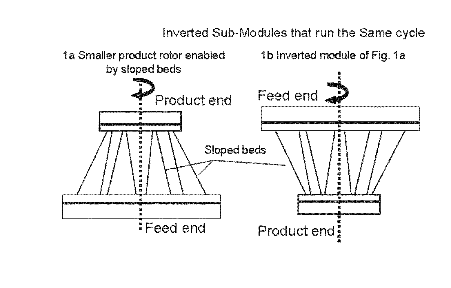
[0089]As discussed above, the various views of FIG. 1 show the use of circumferentially sloped adsorbent beds to allow more efficient use of rotor space. In bulk separation (e.g., CO2 from methane), there can be a relatively large change in gas flow velocity / flux towards the product end during the feed step due to substantial adsorption. To ensure that flow velocity / flux remains within acceptable values, e.g., remains relatively constant, a reduction of adsorbent bed cross-sectional area can be useful, or in some embodiments preferred, for proper operation of bulk separation processes.

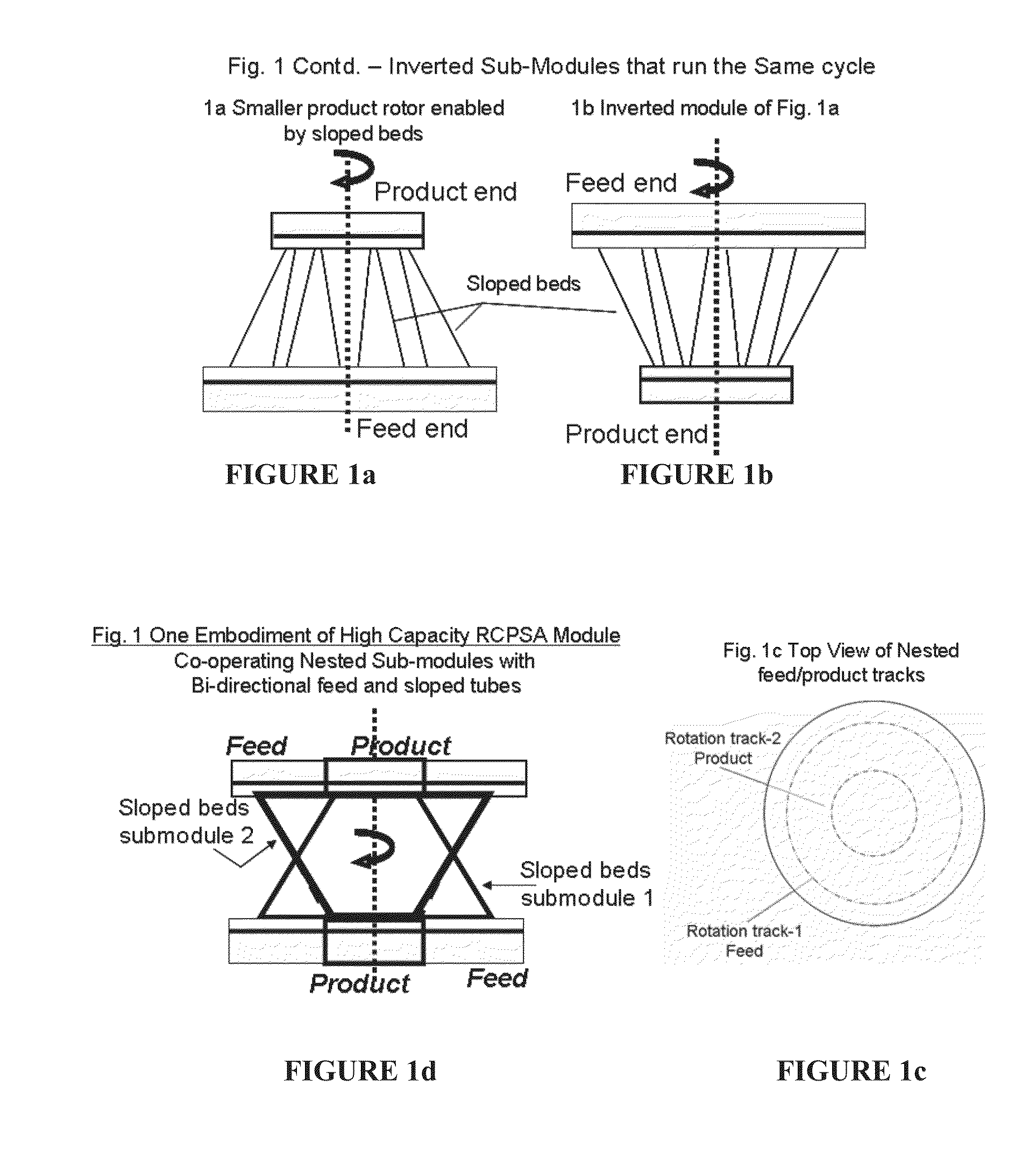
[0090]In FIG. 1, this reduction in adsorbent bed cross-sectional area from feed end to product end can alternately be expressed in terms of the decreasing size / diameter from the feed end rotary valve to the product rotary valve. According to FIG. 1d, these changes in bed cross-sectional area and rotary valve diameter from feed end to product end can be exploited to co-operatively run multiple ...

Example

Example 2

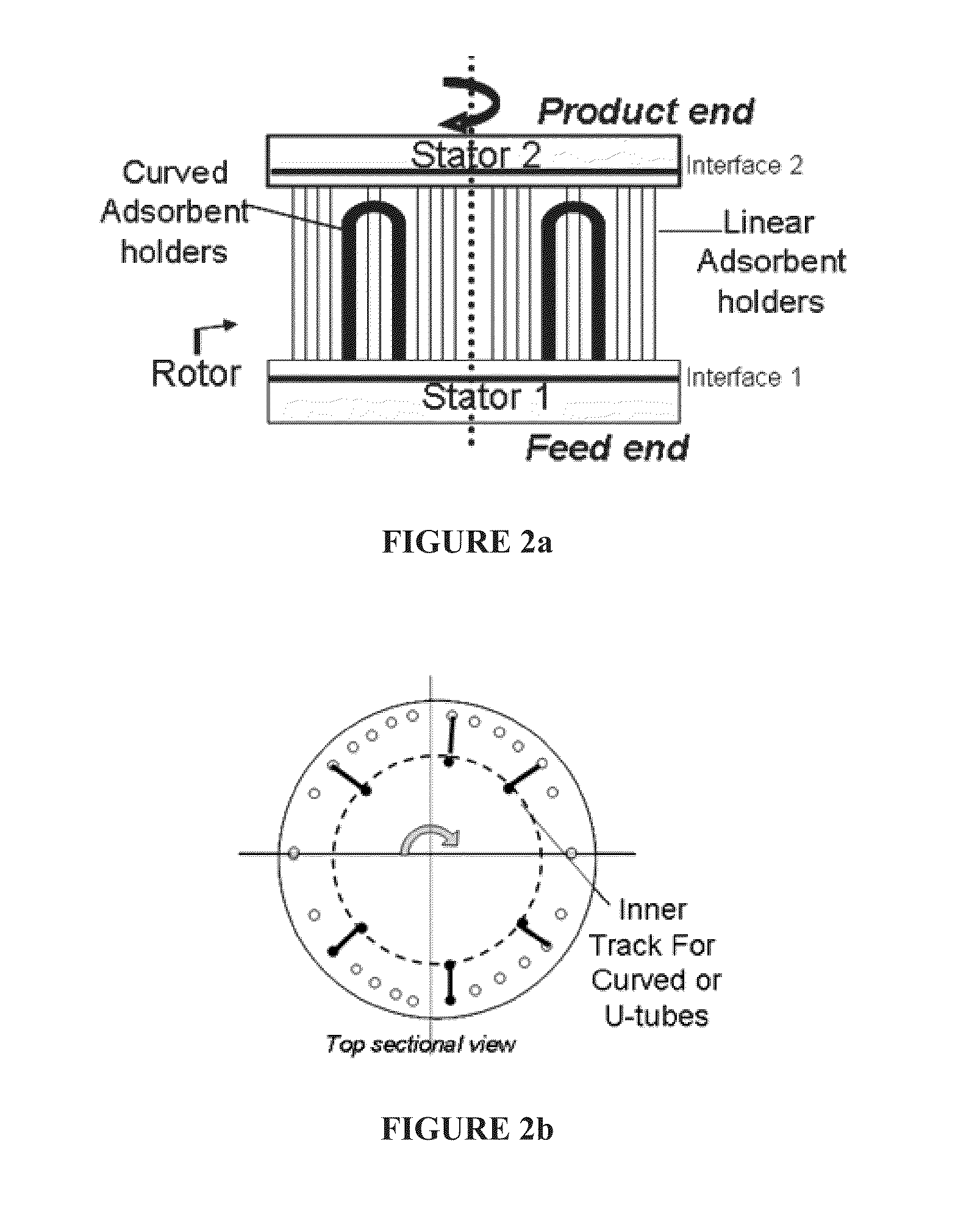
[0094]The various views of FIG. 2 show an embodiment based on modifying a commercial RCPSA module to incorporate a curved tubular adsorbent bed within a rotating valve adsorbent module assembly containing at least a first and a second rotor-stator interface and otherwise linear adsorbent containers disposed between them.

[0095]Though in this configuration of FIG. 2a the first (feed end) and second (product end) rotary valves are roughly the same diameter, the configuration of the curved adsorbent holders creates a situation where the number of rotating plate openings in rotor of the second interface is not equal to the number of the inlet and outlet openings of the adsorbent holders, because the curved (u-shaped) adsorbent holders direct some product effluent back toward the feed end, though on an inner track radially displaced from the linear adsorbent holders. Alternately, the radial displacement of the curved (u-shaped) adsorbent holders can be on an outer track, relative...


PUM


Abstract

The invention relates to an increased efficiency high-capacity pressure and/or temperature swing adsorption process comprising: contacting a feedstream at a rate of more than 75 MSCFD with an adsorbent material under conditions sufficient for the adsorbent material to selectively adsorb at least one of the component gases in the feedstream, so as to form a first effluent; and selectively desorbing the adsorbed gas from the adsorption material, so as to form a second effluent The adsorption module can contain rotary valves both on the feed end and on the product end and a rotational member defining a central rotational axis, with the adsorption bed(s) oriented circumferentially thereto. The adsorption bed walls can be angled, the feed end cross-sectional area of the adsorption bed(s) can be larger than the product end, and/or the feed end rotary valve diameter of the module(s) can be larger than the product end.

Description

FIELD OF THE INVENTION[0001]This invention relates to improvements in swing adsorption processes using a solid adsorbent material and more particularly to improvements in rapid cycle pressure and / or temperature swing adsorption processes to use the solid adsorbent material in a smaller amount and / or more efficiently.BACKGROUND OF THE INVENTION[0002]Natural gas from many gas fields, which is often produced at high pressures, possibly as high as 50 MPa, can contain significant levels of H2O, H2S, CO2, N2, mercaptans, and / or heavy hydrocarbons that have to be removed to various degrees before the gas can be transported to market. It is preferred that as much of the acid gases and CO2 be removed from natural gas as possible to leave methane as the recovered component. Small increases in recovery of this light component can result in significant improvements in process economics and also serve to prevent unwanted resource loss, It is desirable to recover more than 80 vol %, preferably mo...

Claims


Application Information

Patent Timeline
IPC IPC(8): B01D53/04
CPCB01D53/0446B01D53/0462B01D53/047B01D53/06B01D2257/102B01D2257/504B01D2257/702B01D2257/7025B01D2259/40005Y02C20/20Y02C20/40
Inventor SUNDARAM, NARASIMHAN
Owner EXXON RES & ENG CO
Why Eureka
Try Eureka