
Solid state battery fabrication

a technology of solid-state batteries and fabrication methods, applied in the field of liquid-ion batteries, can solve the problems of series stacking difficulty, nominally identical cells having different capacity aging rates, and liquid electrolyte represents a safety hazard, and achieve the effect of scalable and cost-effective suitability

Active Publication Date: 2014-03-06
APPLIED MATERIALS INC
View PDF7 Cites 43 Cited by
  • Summary
  • Abstract
  • Description
  • Claims
  • Application Information

AI Technical Summary

Benefits of technology

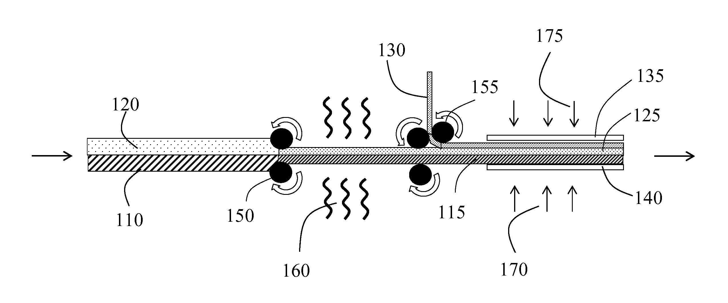
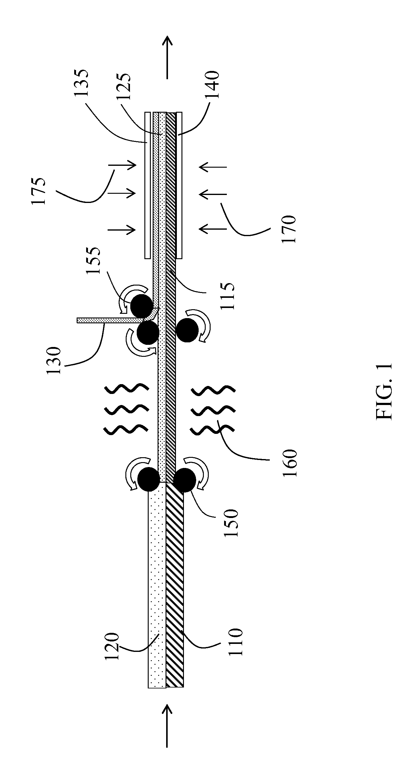
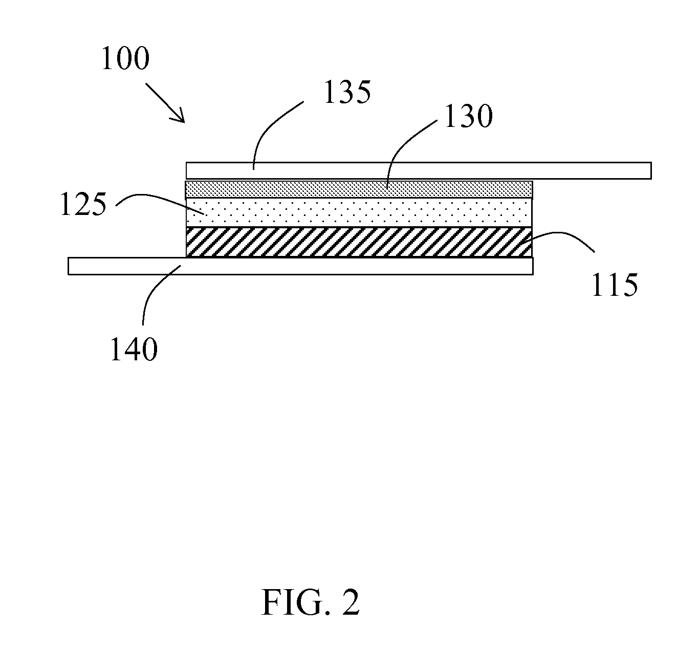
The invention relates to solid state battery structures and methods of fabrication. The fabrication method involves laminating and sintering green sheets of electrodes and separators. The resulting sintered stack includes a positive electrode with a separator between it and a negative electrode. The method is scalable and cost-effective. The invention also includes a process system for solid state battery fabrication. The technical effects of the invention include high performance and durable solid state batteries with improved safety and reliability.

Problems solved by technology

In these Li-ion batteries, the liquid electrolyte represents a safety hazard because it is flammable and reacts with the other cell components.
Shorting of the negative electrode to the positive electrode can cause a fire.
Also, reactions between the electrolytes and the other active materials in the cell can result in nominally identical cells having different rates of capacity aging.
This makes series stacking difficult as the imbalance reduces the available capacity of the series stack and can result in safety issues—for example, over charging of some cells in the battery due to stacking of cells with different capacities may cause premature failure or thermal runaway of overcharged cells.
All of these measures add expense and reduce the energy density at the cell and pack level.

Method used


Image

  • Solid state battery fabrication
  • Solid state battery fabrication
  • Solid state battery fabrication

Examples


Embodiment Construction

[0012]Embodiments of the present invention will now be described in detail with reference to the drawings, which are provided as illustrative examples of the invention so as to enable those skilled in the art to practice the invention. Notably, the figures and examples below are not meant to limit the scope of the present invention to a single embodiment, but other embodiments are possible by way of interchange of some or all of the described or illustrated elements. Moreover, where certain elements of the present invention can be partially or fully implemented using known components, only those portions of such known components that are necessary for an understanding of the present invention will be described, and detailed descriptions of other portions of such known components will be omitted so as not to obscure the invention. In the present specification, an embodiment showing a singular component should not be considered limiting; rather, the invention is intended to encompass ...


PUM

PropertyMeasurementUnit
Electrical conductoraaaaaaaaaa

Abstract

Embodiments of the invention generally relate to solid state battery structures, such as Li-ion batteries, methods of fabrication and tools for fabricating the batteries. One or more electrodes and the separator may each be cast using a green tape approach wherein a mixture of active material, conductive additive, polymer binder and / or solid electrolyte are molded or extruded in a roll to roll or segmented sheet / disk process to make green tape, green disks or green sheets. A method of fabricating a solid state battery may include: preparing and / or providing a green sheet of positive electrode material; preparing and / or providing a green sheet of separator material; laminating together the green sheet of positive electrode material and the green sheet of separator material to form a laminated green stack; and sintering the laminated green stack to form a sintered stack comprising a positive electrode and a separator.

Description

CROSS-REFERENCE TO RELATED APPLICATIONS[0001]This application claims the benefit of U.S. Provisional Application No. 61 / 694,198 filed Aug. 28, 2012, incorporated herein by reference in its entirety.FIELD OF THE INVENTION[0002]Embodiments of the present invention relate generally to Li-ion batteries and more specifically to solid state Li-ion batteries fabricated using a “green tape” lamination and sintering process to form the positive electrode, separator and negative electrode stack.BACKGROUND OF THE INVENTION[0003]The current generation of Li-ion batteries use liquid electrolyte; although, from a safety perspective a solid state electrolyte would be preferred. The current generation of Li-ion batteries consist of a positive electrode and a negative electrode separated by a porous separator and liquid electrolyte used as the ionic conductive matrix. In these Li-ion batteries, the liquid electrolyte represents a safety hazard because it is flammable and reacts with the other cell c...

Claims


Application Information

Patent Timeline
IPC IPC(8): H01M10/0585H01M10/04
CPCH01M10/0585H01M10/0436H01M10/0413H01M10/0468H01M10/052H01M10/0562H01M2300/0071H01M4/0471Y02P70/50Y02E60/10H01M10/054H01M10/14B32B18/00B29C65/02C04B35/52C04B35/01C04B2235/3203C04B37/00C04B37/001C04B37/003C04B2237/08C04B2237/16Y02T10/70
Inventor HERLE, SUBRAMANYA P.GORDON, II, JOSEPH G.
Owner APPLIED MATERIALS INC
Learn More