Liquid crystal display panel

a liquid crystal display and display panel technology, applied in non-linear optics, instruments, optics, etc., can solve problems such as light leakage of liquid crystal displays, and achieve the effects of reducing incident angles, reducing incident angles, and increasing shift angles

Inactive Publication Date: 2014-03-06
INNOLUX CORP
View PDF6 Cites 3 Cited by
  • Summary
  • Abstract
  • Description
  • Claims
  • Application Information

AI Technical Summary

Benefits of technology

[0015]When the protruding electrode layer is composed of a non-conductive organic material, the light leakage-proof unit of the liquid crystal display panel according to the present invention may be a multilayer film. After the oblique incidence of light, a change in transmittance of TE and/or TM wave results in a shift of the polarization direction, thereby causing the light leakage. In this case, the greater the incident angle, the greater the shift angle and the more serious the light leakage. Accordingly, the light path is changed by the multilayer film, to reduce the incident angles and improve the light leakage. Preferably, a light incidence form a high refractive index medium to a low refractive index medium is prevented. In addition, when the inclined plane slope of the protruding electrode layer is nearly horizontal (the absolute value of the inclined plane slope is 0 to 0.15), the light leakage is less serious at this area, and the submicron structure layer has an opening corresponding to this area of the protruding electrode layer.
[0016]When the protruding electrode layer is composed of a non-conductive organic material, the light leakage-proof unit of the liquid crystal display panel according to the present invention may be a micro-reflection layer. T

Problems solved by technology

In addition, the multilayer film structure of the protruding electrode layer has a problem of refractive index mismatch, and an amplit

Method used


Image

  • Liquid crystal display panel
  • Liquid crystal display panel
  • Liquid crystal display panel

Examples


example 2

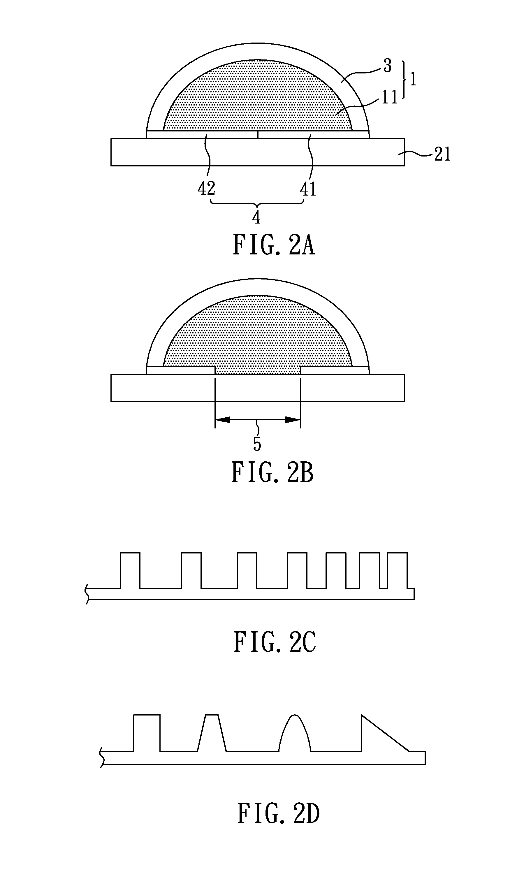
[0034]FIG. 2A shows a schematic diagram of the protruding electrode layer with the submicron structures. A protruding part 11 is formed on the glass substrate 21 by using the organic materials, such as fluorinated ethylene propylene copolymer: perfluoro ethylene propylene copolymer, poly(perfluoro ethylene propylene); or tetrafluoroethylene-perfluoroalkoxy vinyl ether copolymer, and then an ITO is coated thereon to serve as an electrode layer 3. In this case, the cross-sectional shape of the protruding electrode layer 1 is semicircular (but the present invention is not limited thereto, the cross-section shape may also be of other shapes such as the semi-elliptical shape). In addition, a submicron structure layer 4 is further disposed between the protruding electrode layer 1 and the glass substrate 21, wherein the submicron structure layer 4 includes the symmetric submicron structure units 41, 42 as shown in FIG. 2C or 2D. Referring to FIG. 2C, the arrangement of the submicron struct...

example 3

[0036]FIG. 2B shows a schematic diagram of the protruding electrode layer with the submicron structures. The same manufacturing process as in Example 2 is carried out, except that the middle of the submicron structure units 41, 42 of the submicron structure layer 4 has an opening 5 which corresponds to the center of protruding electrode layer 1 (more gentle region).

example 4

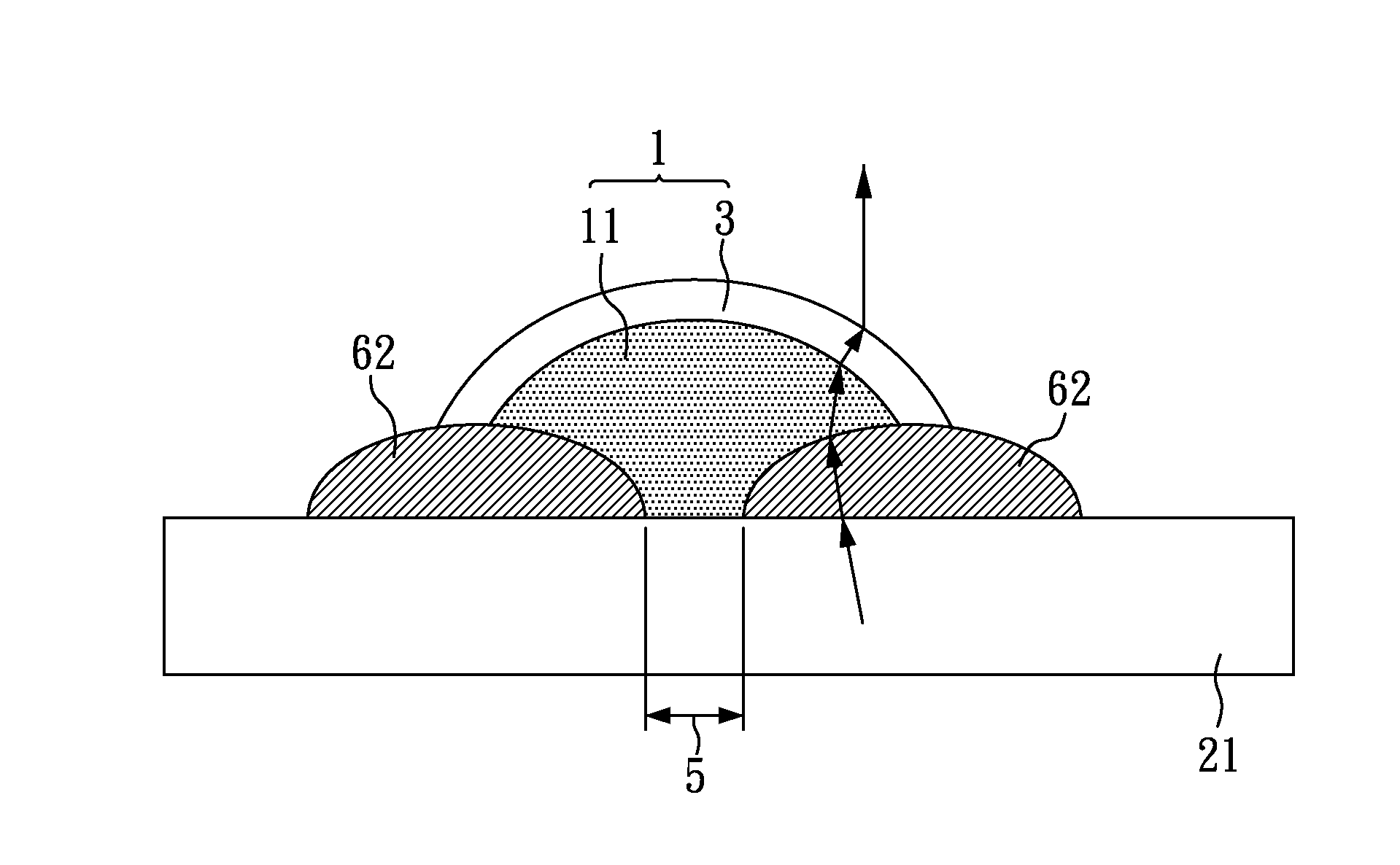
[0037]FIG. 4A shows a schematic diagram of the protruding electrode layer with the multilayer film. A protruding part 11 is formed on the glass substrate 21 using the organic materials, such as fluorinated ethylene propylene copolymer: perfluoro ethylene propylene copolymer, poly(perfluoro ethylene propylene); or tetrafluoroethylene-perfluoroalkoxy vinyl ether copolymer, then an ITO is coated thereon to serve as an electrode layer 3; in the current case, the cross-sectional shape of the protruding electrode layer 1 is semicircular (but the present invention is not limited thereto, the cross-sectional shape may also be of other shapes such as the semi-elliptical shape). In addition, a multilayer film 61 is further disposed between the protruding electrode layer 1 and the glass substrate 21. As shown in FIG. 4A, the light path is indicated by the arrowhead, and the light path may be adjusted by its interfaces with different refractive indexes to reduce the incident angle, thereby lowe...


PUM


Abstract

A liquid crystal display panel is disclosed, which comprises: a first substrate; a second substrate opposite to the first substrate; an optically isotropic liquid crystal layer disposed between the first substrate and the second substrate; and a protruding electrode layer composed of a polymer conductive material and disposed on the first substrate. Besides, when a protruding part is composed of a non-conductive organic material, the liquid crystal display panel further comprises: an electrode layer disposed on the protruding electrode layer; and a submicron structure layer, a multilayer film, or a micro-reflection layer is disposed between the protruding electrode layer and the first substrate.

Description

TECHNICAL FIELD[0001]The present invention relates to a liquid crystal display panel, and more particularly to a liquid crystal display panel comprising a protruding electrode layer composed of a polymer conductive material; and a liquid crystal display panel using a submicron structure layer, a multilayer film, or a micro-reflection layer to improve the light leakage.BACKGROUND ART[0002]A liquid crystal display (LCD) is a flat thin display device, which has replaced the traditional cathode ray tube display and become one of the most popular display device in recent years for its thin shape, light weight, and low power consumption. A liquid crystal display has been widely used over small portable terminal devices to large size TVs due to its advantageous characteristics.[0003]Blue phase liquid crystal has a self-aggregated three-dimensional photonic crystal structure, wherein the blue phase appears between the isotropic phase and the cholesteric phase at a temperature ranging from 0...

Claims


Application Information

Patent Timeline
IPC IPC(8): G02F1/1335
CPCG02F1/133512G02F1/13439G02F1/13793
Inventor CHEN, YU-WEICHEN, CHIEN-HUNG
Owner INNOLUX CORP
Why Eureka
Try Eureka