Substrate Transferred Monocrystalline Bragg Mirrors

a monocrystalline bragg mirror and substrate technology, applied in the direction of optics, instruments, optical elements, etc., to achieve the effect of reducing mechanical damping in the mirror materials

Active Publication Date: 2014-03-06
THORLABS INC
View PDF1 Cites 6 Cited by
  • Summary
  • Abstract
  • Description
  • Claims
  • Application Information

AI Technical Summary

Benefits of technology

[0003]The present invention provides an alternative solution to overcome the above-menti

Problems solved by technology

However, a monocrystalline material does not contain grain boundaries and defects associated with sai

Method used


Image

  • Substrate Transferred Monocrystalline Bragg Mirrors
  • Substrate Transferred Monocrystalline Bragg Mirrors
  • Substrate Transferred Monocrystalline Bragg Mirrors

Examples


Embodiment Construction

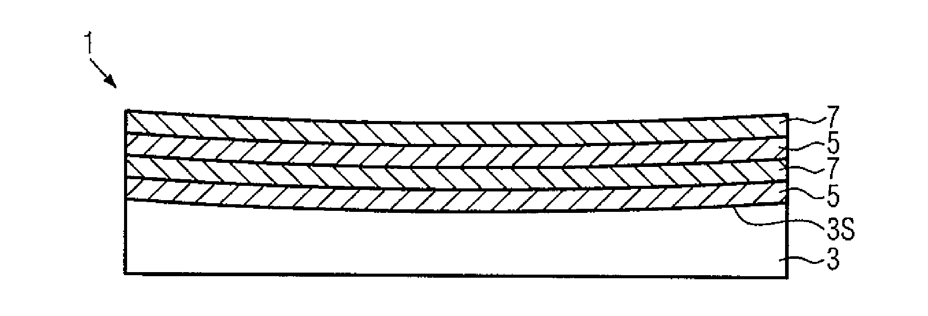
[0040]FIG. 1 shows a side view of a low absorption mirror assembly according to the present invention.

[0041]The stack comprises a monocrystalline Bragg mirror bonded to a curved carrier substrate. As described previously, in this application the term monocrystalline refers to a low defect density single-crystal film as can be produced via epitaxial growth techniques, MBE, MOVPE, LPE, etc. In this document crystalline and monocrystalline may be used interchangeably. The mirror assembly 1 of FIG. 1 is only schematically depicted. A curved substrate 3 is provided as the carrier substrate for a stack of monocrystalline layers. The stack 9 of layers 5 and 7 is depicted in a simplification with only four layers, it should be understood, however, that the stack 9 typically comprises many more layers. The maximum reflectivity may be determined by the total number of layers—asymptotically approaching a reflectivity value of 100%. The number of layers for the present example may be about 40 p...


PUM


Abstract

A mirror assembly comprising a carrier substrate; a stack comprising a plurality of alternating monocrystalline semiconductor layers of a first and a second type, wherein the layers of the first type have an index of refraction higher than the layers of the second type thereby forming a Bragg mirror; wherein the carrier substrate is curved having a radius of curvature between 0.1 m and 10 km; wherein the stack is attached to the curved carrier substrate.

Description

FIELD OF THE INVENTION[0001]The present invention relates to a mirror assembly based on a monocrystalline Bragg mirror bonded to a curved carrier substrate and a process of manufacturing the mirror assembly and an optical resonator system comprising a pair of mirror assemblies forming an optical cavity for application in optical precision measurement systems.BACKGROUND OF THE INVENTION[0002]Current state-of-the-art multilayer mirrors consist of stacks of dielectric materials, with typical structures using amorphous SiO2 / Ta2O5 films deposited via ion beam sputtering, IBS. These materials allow for remarkable optical properties showing total absorption less than 1 ppm at a wavelength of 1064 nm. However, recent requirements with respect to the ultimate sensitivity of high performance optical devices such as gravitational wave interferometers and optical reference cavities show that such films exhibit excessively large mechanical dissipation. This dissipation is one of the major factor...

Claims


Application Information

Patent Timeline
IPC IPC(8): G02B5/28H01L33/60G02B5/08
CPCG02B5/288H01L33/60G02B5/0816G02B5/0833G01N21/31
Inventor ASPELMEYER, MARKUSCOLE, GARRETT
Owner THORLABS INC
Why Eureka
Try Eureka