
Redox and plating electrode systems for an all-iron hybrid flow battery

a technology of redox and plating electrodes, applied in the direction of electrochemical generators, cell components, indirect fuel cells, etc., can solve the problems of unfavorable ion exchange, unfavorable ion exchange rate, and the primary source of ifb performance loss of plating reaction at the negative electrode, so as to maximize the capacity and performance of a hybrid flow battery. , the effect of limiting the overall battery capacity

Active Publication Date: 2014-03-06
ESS TECHNOLOGY
View PDF5 Cites 38 Cited by
  • Summary
  • Abstract
  • Description
  • Claims
  • Application Information

AI Technical Summary

Benefits of technology

The patent text describes a system for improving the performance and capacity of a hybrid flow battery by addressing the issues of limited plating surface area and mass transport losses. The system includes a redox plate with a plurality of electrolyte flow channels and conductive inserts attached between adjacent channels. The system also includes a plating electrode with a plurality of folded fins and a membrane barrier between the plating electrode and the redox electrode. The system can maximize the battery's performance by decreasing reaction kinetics, mass transport, and ohmic resistance losses at both the plating and redox electrodes.

Problems solved by technology

However, by pumping electrolytes through graphite flow channels, unnecessary reactions may occur on both the surface of the channels and the surface of the electrode, leading to unnecessary ohmic losses.
Further, an all-graphite or C / Graphite composite channels cannot be formed by inexpensive manufacturing methods such as injection molding.
The plating reaction at the negative electrode is the primary source of the IFB performance loss, as a result of the plating kinetics, resistance, and mass transport losses.
Limited plating surface area thus results in higher overpotential on the negative electrode in order for the reaction to occur, while a limited plating volume may limit the overall battery capacity.

Method used


Image

  • Redox and plating electrode systems for an all-iron hybrid flow battery
  • Redox and plating electrode systems for an all-iron hybrid flow battery
  • Redox and plating electrode systems for an all-iron hybrid flow battery

Examples


Embodiment Construction

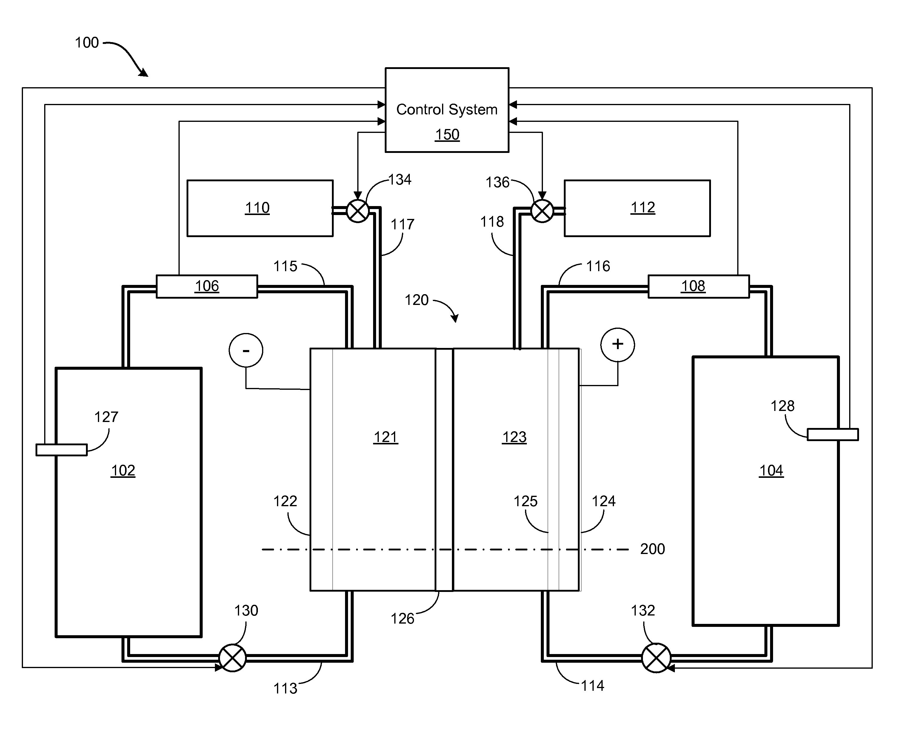
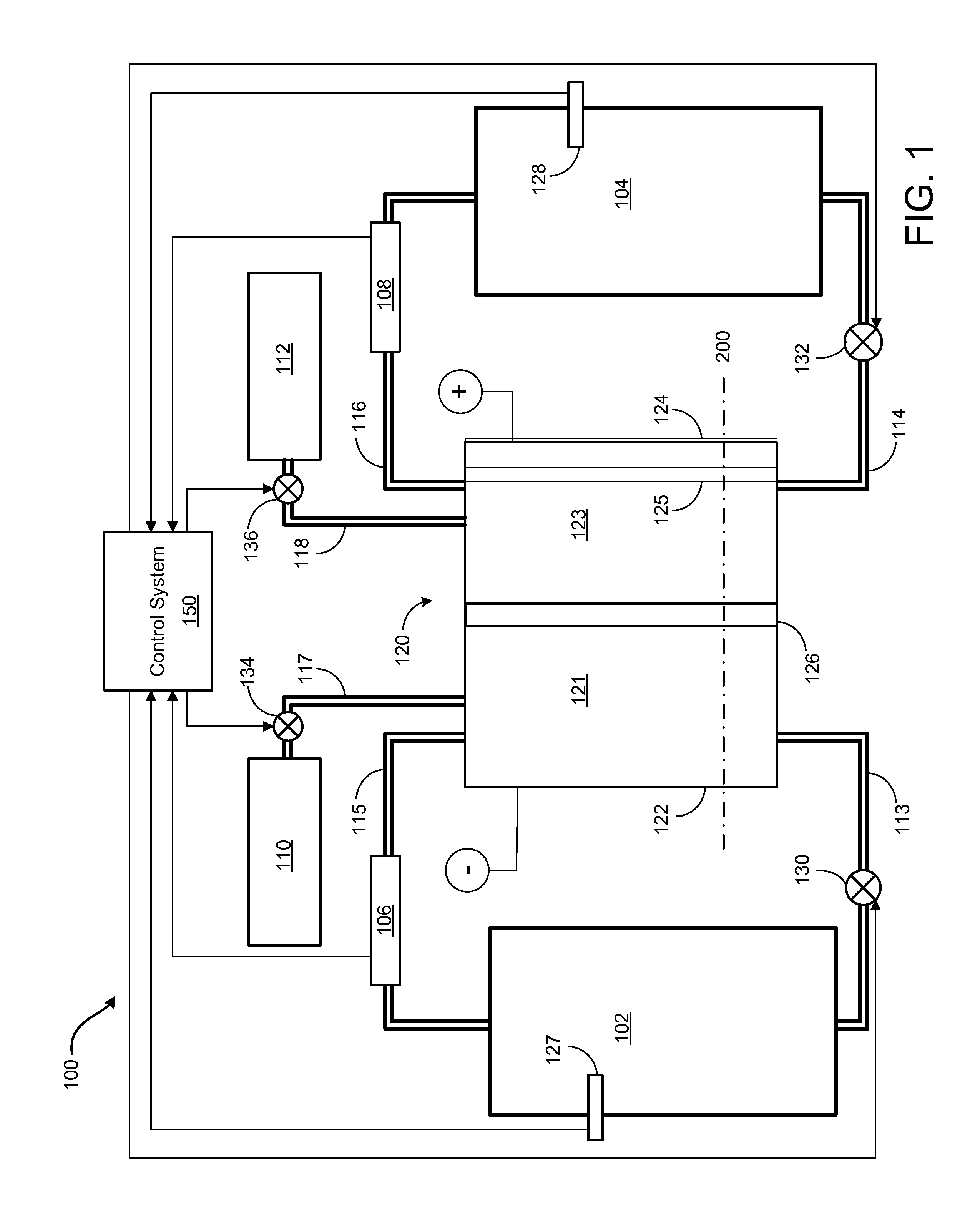
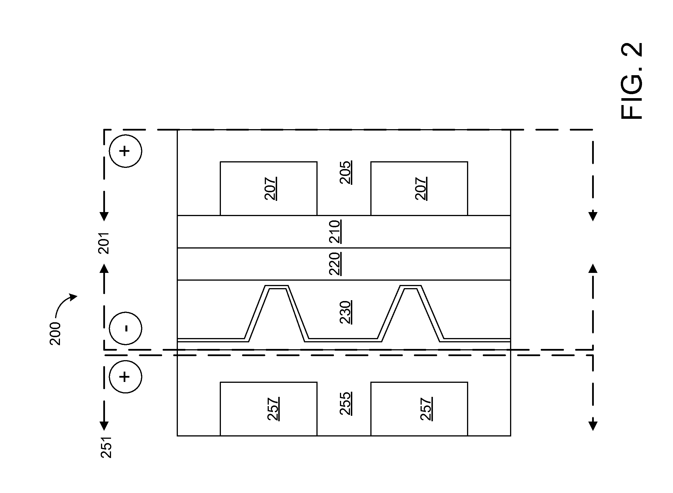
[0030]The following description relates to systems for an all-iron hybrid flow battery (IFB), such as the IFB schematically depicted in FIG. 1. The IFB may include redox and plating electrodes, membrane barriers, and redox and plating plates, as diagrammed in FIG. 2. The plating electrode may comprise a folded fin design, as shown in FIGS. 3A, 3B, 3C, 3D, 4A, 4B, and 4C. The plating electrode fins may comprise perforations, as shown in FIGS. 4A and 4C. The redox plate may include a robust polymer plate as well as C / Graphite composite inserts, as shown in FIGS. 5A and 5B. The redox and plating plates may further comprise interdigitated flow fields as shown in FIG. 6A. The flow channels may be stepped as shown in FIG. 6B, or sloped as shown in FIG. 6C. The redox and plating plates may be included in an internally manifold flow cell, as shown in FIGS. 7A and 7B. A plurality of flow cells may be assembled into a flow cell stack, as shown in FIG. 8A. The flow cell of FIG. 7A and the flow...


PUM

PropertyMeasurementUnit
lengthaaaaaaaaaa
conductiveaaaaaaaaaa
widthaaaaaaaaaa

Abstract

A system for a flow cell for a hybrid flow battery, comprising: a redox plate comprising a plurality of electrolyte flow channels; conductive inserts attached to the redox plate between adjacent electrolyte flow channels; a redox electrode attached to a surface of the redox plate; a plating electrode, comprising: a plurality of folded fins with an oscillating cross-section, the plurality of folded fins comprising: a first planar surface; a second planar surface, parallel to the first planar surface; a plurality of ridges intersecting the first and second planar surfaces such that the plurality of ridges divide the first planar surface into a first plurality of strips, and divide the second planar surface into a second plurality of strips; and a membrane barrier. In this way, the capacity and performance of hybrid flow batteries may be maximized, through decreasing the reaction kinetics, mass transport and ohmic resistance losses at both electrodes.

Description

CROSS REFERENCE TO RELATED APPLICATIONS[0001]The present application is a non-provisional of and claims priority to U.S. Provisional Application No. 61 / 697,202 filed Sep. 5, 2012 entitled, “All Iron Hybrid Flow Battery,” and is a non-provisional of and claims priority to 61 / 778,160 filed Mar. 12, 2013 entitled, “Plating and Redox Electrode System and Design for an All Iron Redox Flow Battery,” the entire contents of each of which are hereby incorporated by reference for all purposes.BACKGROUND AND SUMMARY[0002]The reduction-oxidation (redox) flow battery is an electrochemical storage device that stores energy in a chemical form and converts the stored chemical energy to an electrical form via spontaneous reverse redox reactions. Due to the decoupling of the electrolyte (energy capacity) from the stack (power module), a flow battery offers the ability to change energy storage capacity without altering the entire system, the ability to increase maximum power output with minimal system...

Claims


Application Information

Patent Timeline
Patent Type & Authority Applications(United States)
IPC IPC(8): H01M8/18H01M8/20
CPCH01M8/20H01M8/188Y02E60/50Y02E60/10Y10T137/4757H01M50/60H01M8/04186
Inventor EVANS, CRAIGSONG, YANG
Owner ESS TECHNOLOGY
Learn More