
Microphone with Parasitic Capacitance Cancelation

a technology of parasitic capacitance and microphone, which is applied in the field of microphones, can solve the problems of parasitic capacitance between the backplate and the diaphragm of the microphone, limiting the sensitivity and requiring significant complexity and power, so as to improve the performance of the mems microphone and eliminate parasitic capacitan

Active Publication Date: 2014-03-13
INVENSENSE
View PDF3 Cites 5 Cited by
  • Summary
  • Abstract
  • Description
  • Claims
  • Application Information

AI Technical Summary

Benefits of technology

The patent text describes a way to make MEMS microphones better by getting rid of unwanted electrical signals. This is done by creating a second capacitor that acts as a reference for the unwanted signals. By removing this reference, the microphone can produce a cleaner signal with less noise.

Problems solved by technology

One significant limiting factor to the sensitivity of a MEMS microphone, however, is parasitic capacitance between the backplate and diaphragm of the microphone.
Undesirably, those approaches require significant complexity and power.
Accordingly, these solutions often increase overall cost of the ultimate device.
When used in applications with limited power supplies (e.g., in hearing instruments, which often have very small batteries), these solutions reduce battery lifetime.

Method used


Image

  • Microphone with Parasitic Capacitance Cancelation
  • Microphone with Parasitic Capacitance Cancelation
  • Microphone with Parasitic Capacitance Cancelation

Examples


first embodiment

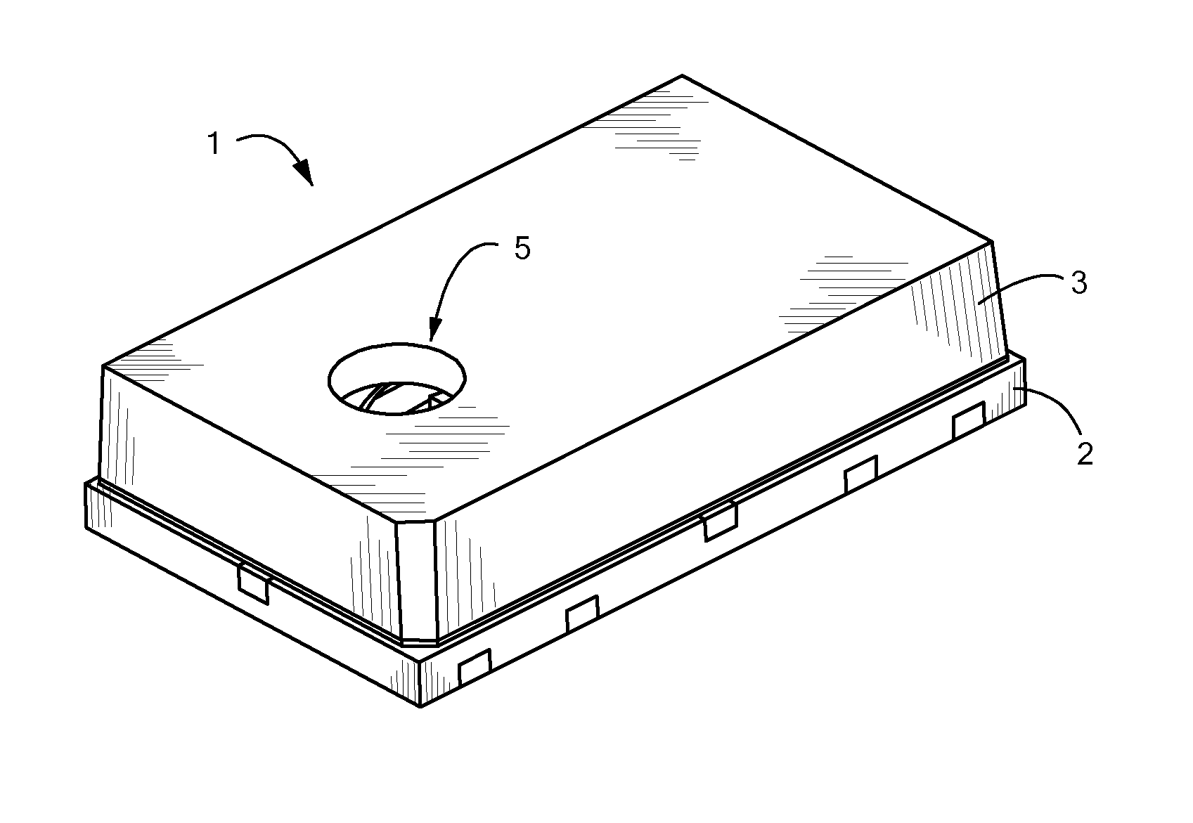
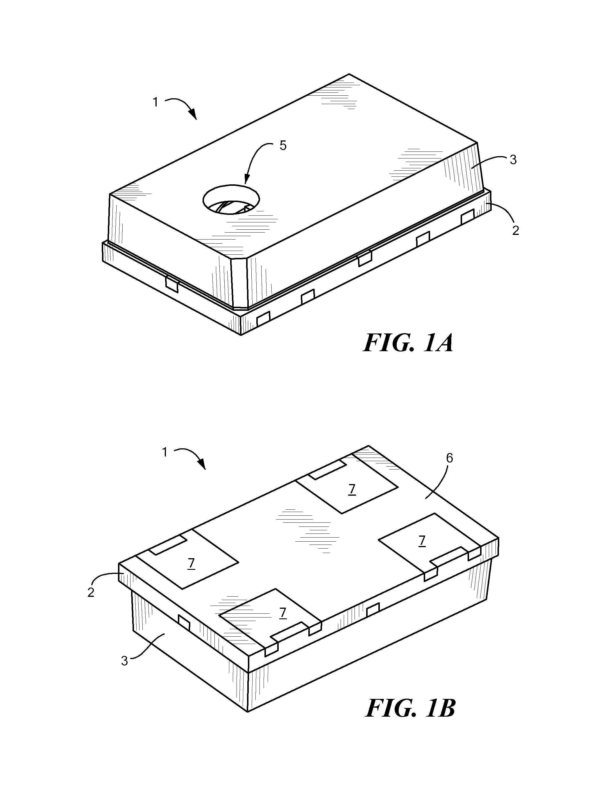
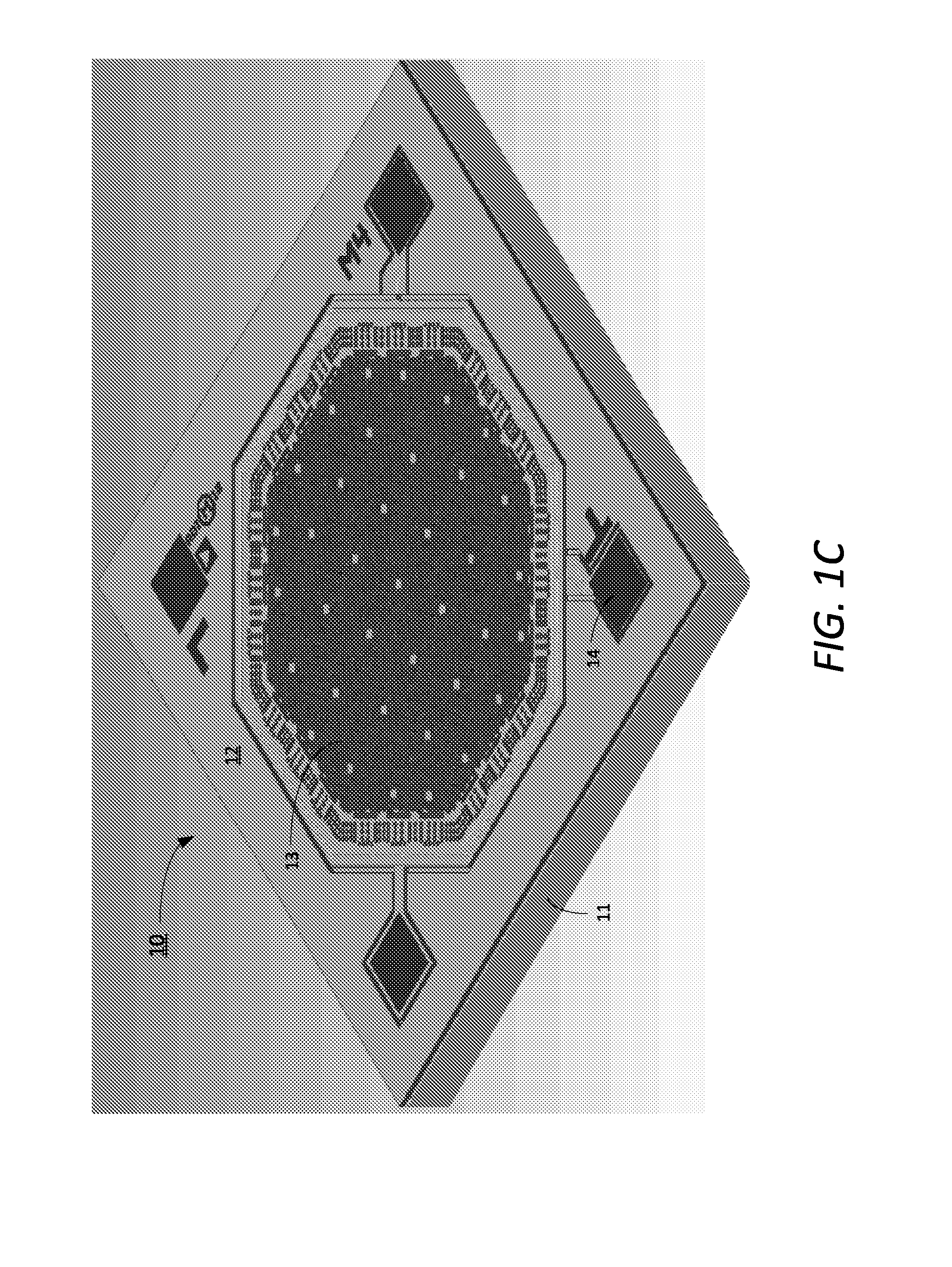
[0005]In accordance with the invention, a MEMS microphone has a diaphragm, a backplate, a sensor, a reference electrode, and a circuit. The diaphragm is moveably coupled with an anchor, and the anchor is fixedly coupled to a substrate. The backplate is separated from the diaphragm by a dielectric fluid, and is fixedly coupled to the anchor by a dielectric solid. There is a first capacitance between the backplate and the diaphragm, and a second capacitance between the backplate and the anchor. The sensor measures a capacitance between the backplate and the diaphragm. This capacitance is substantially equal to the sum of the first capacitance and the second capacitance. The reference electrode is embedded within the dielectric solid. There is a third capacitance between the reference electrode and the backplate that is substantially the same as the second capacitance. The circuit subtracts the third capacitance from the capacitance measured by the sensor to produce an output capacitan...

second embodiment

[0007]In accordance with the invention, a MEMS microphone has a backplate, an anchor, a diaphragm, a reference capacitor, and a circuit. The backplate and the anchor produce a parasitic capacitance. The diaphragm is movably secured to the anchor and spaced from the backplate, so that the diaphragm and backplate form a variable capacitor having a primary capacitance. The reference capacitor has a reference capacitance that is substantially equal to the parasitic capacitance. The circuit has an input that receives the primary capacitance, parasitic capacitance, and the reference capacitance. The circuit is configured to subtract the parasitic capacitance from the primary capacitance and the parasitic capacitance to produce an output capacitance substantially equal to the primary capacitance.

[0008]The MEMS microphone system of the second embodiment may have a first die and a second die, the first die including the variable capacitor and reference capacitor, the second die including the...


PUM

PropertyMeasurementUnit
capacitanceaaaaaaaaaa
dielectricaaaaaaaaaa
parasitic capacitanceaaaaaaaaaa

Abstract

A microelectromechanical microphone and method of manufacturing the same are disclosed. The microphone has a moveable diaphragm and a fixed backplate that create a variable capacitance. A fixed anchor electrically coupled to the diaphragm has an electrode that measures the variable capacitance, but also measures an unwanted, additive, parasitic capacitance. Various embodiments include a reference electrode, manufactured in the same deposition layer as the diaphragm or anchor, that measures only the parasitic capacitance. A circuit is provided either on-chip or off-chip that subtracts the capacitance measured at the reference electrode from that measured at the anchor, thereby producing only the desired variable capacitance as output. Because the reference electrode is deposited at the same time as the diaphragm or anchor, only minimal changes are required to existing manufacturing techniques.

Description

TECHNICAL FIELD[0001]The present invention relates to microphones and more particularly to controlling parasitic capacitance in MEMS microphones.BACKGROUND ART[0002]Microelectromechanical systems (MEMS) microphones are widely used in voice communications, hearing-aid devices, and noise and vibration control applications. Various micromachining technology has been used to design and fabricate various MEMS microphones. Due to its high sensitivity, high signal-to-noise ratio (SNR), and long-term stability performance, the capacitive microphone is a very desirable and widely used type of microphone.[0003]One significant limiting factor to the sensitivity of a MEMS microphone, however, is parasitic capacitance between the backplate and diaphragm of the microphone. Much of the research and development on solving this problem has focused on software calibration methods, including noise-reduction algorithms, and second-order directional microphones. Undesirably, those approaches require sig...

Claims


Application Information

Patent Timeline
Patent Type & Authority Applications(United States)
IPC IPC(8): H04R1/00H04R31/00
CPCH04R3/06H04R19/005Y10T29/43
Inventor LIU, FANGYANG, KUANG L.
Owner INVENSENSE
Learn More