

Method for operating an air conditioner for a motor vehicle
- Summary
- Abstract
- Description
- Claims
- Application Information
AI Technical Summary
Benefits of technology
Problems solved by technology
Method used
Image

Examples
first embodiment
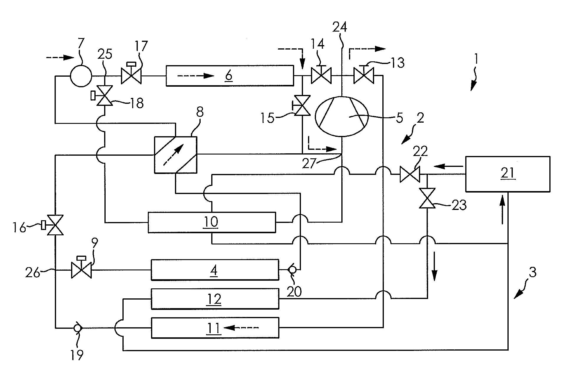
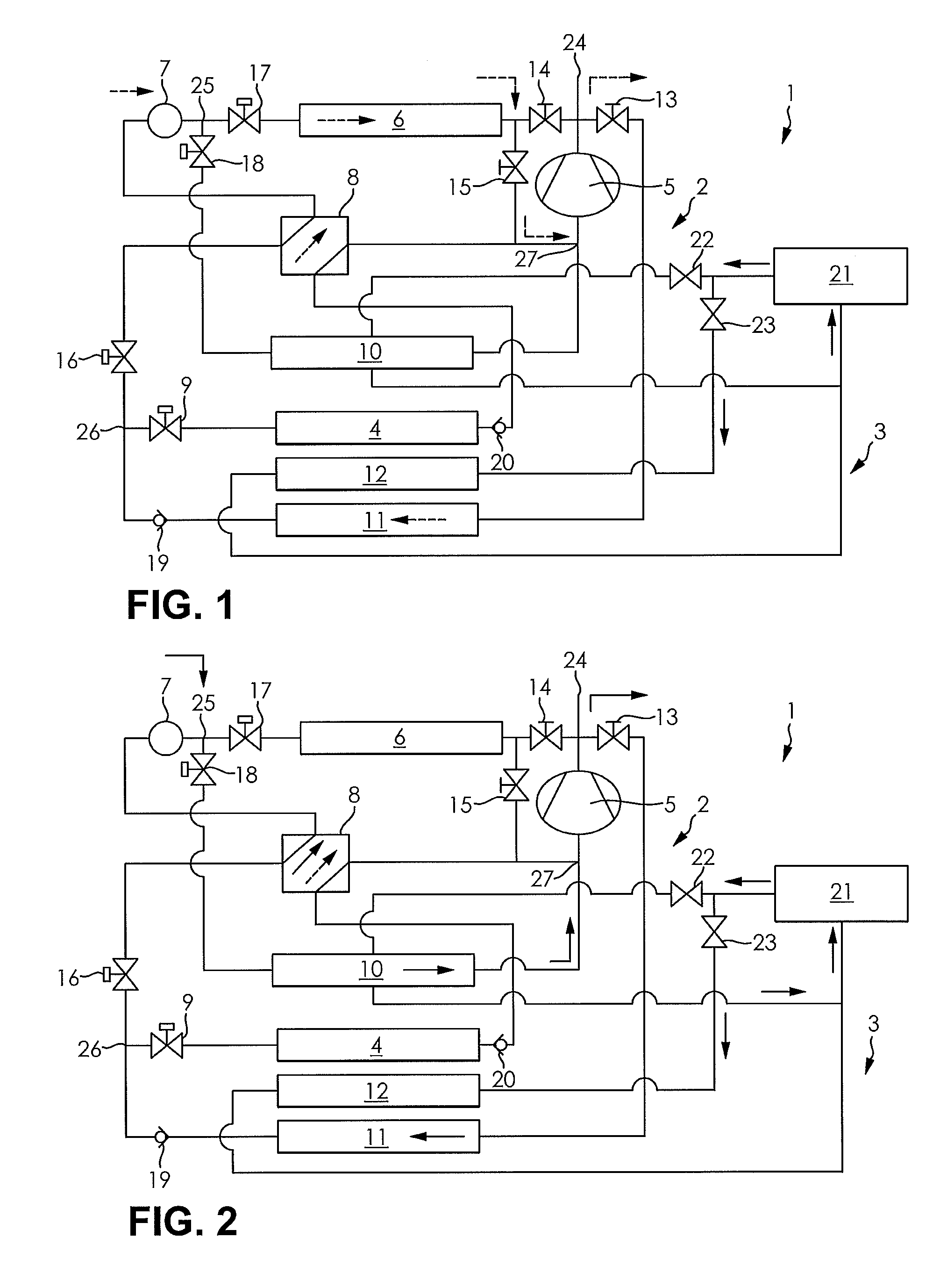
[0156] the switchover process starts by opening the expansion valve 17, so that expansion valve 17 is opened in the flow direction of the refrigerant before heat exchanger 6, and the expansion valve 18 before heat exchanger 10 is simultaneously opened for a duration of 5 to 60 seconds. During the switchover, both heating warmth exchanger 12 and heat exchanger 10 in engine coolant circuit 3 have coolant flowing through them.
[0157]With the closing of expansion valve 18, the shutoff valve 22 to heat exchanger 10 is also closed, so that only heating warmth exchanger 12 has coolant flowing through it.
second embodiment
[0158] the switchover occurs through simultaneous closing of expansion valve 18 and opening of expansion valve 17. At the start of the switchover process, in addition the shutoff valve 22 of engine cooling circuit 3 within the line to heat exchanger 10 is closed, so that in turn only the heating warmth exchanger 12 has coolant flowing through it.
[0159]The operation of the air conditioner 1 can be switched over from the heat-pump mode with air as the heat source into the heat-pump mode with coolant as the heat source, switched back or again switched on, if the comfort in the passenger compartment cannot be attained with operation in the heat-pump mode with air as the heat source.
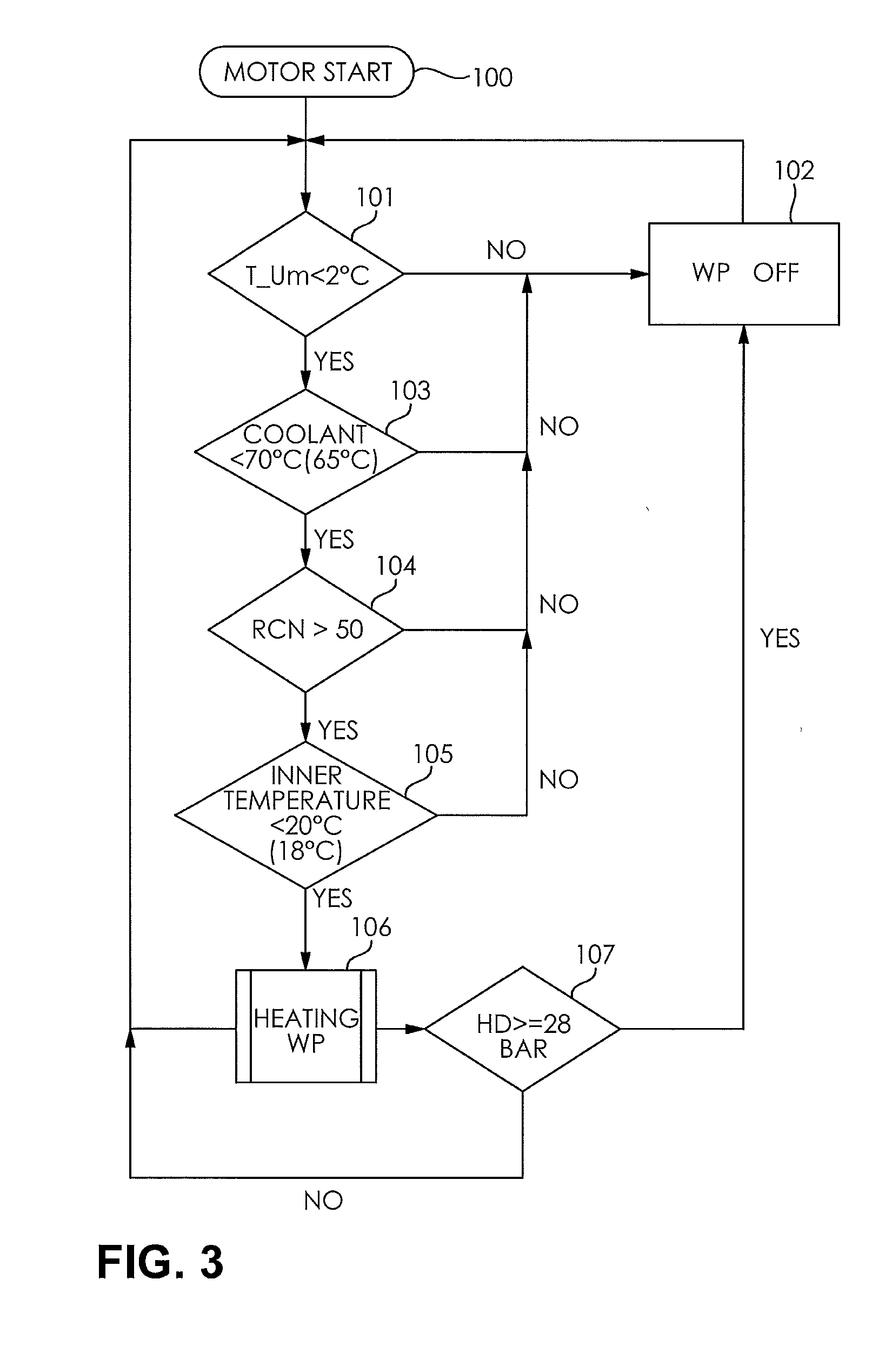
[0160]There is no switchover into the heat-pump mode with coolant as the heat source, if the temperature of the coolant as per step 110 or step 112 is higher than or equal to 50° C., to avoid peaks in maximum pressure. Avoidance of maximum pressure peaks is especially aimed at the usage of mechanical compress...
third embodiment
[0164] when the air conditioner 1 is operated in the heat-pump mode with coolant as the heat source, the engine cooling circuit is switched over so that only coolant still flows through the heating warmth exchanger 12 and the heat exchanger 10 is cooled off or down by the refrigerant continuing to flow through. Thereby the suction pressure of the coolant in the refrigerant circuit 2, and thus, also the performance, is reduced. As soon as the suction pressure in refrigerant circuit 2, when operated in the heat-pump mode with coolant as the heat source, has approached the suction pressure to be expected when operating in the heat-pump mode with air as the heat source, i.e., the ambient temperature level, then a switchover can be made with no appreciable pressure difference from the lower pressure level of the heat-pump mode with air as a heat source to the heat-pump mode with coolant as the heat source.
PUM
 Abstract
Description
Claims
Application Information