
Photoelectric conversion element, method of manufacturing photoelectric conversion element, and electronic device

Active Publication Date: 2014-03-20
SEIKO EPSON CORP
View PDF1 Cites 7 Cited by
  • Summary
  • Abstract
  • Description
  • Claims
  • Application Information

AI Technical Summary

Benefits of technology

The patent describes a method of manufacturing a photoelectric conversion element and a photoelectric conversion element itself. The method involves using wet etching to selectively pattern a conductive film and to prevent corrosion of other film layers. The element includes a second conductive film which is surrounded by a first conductive film and a metal compound film, which helps prevent leakage of electrical current and film peeling. The use of a metal compound film with p type characteristics increases the photoelectric conversion efficiency compared to silicon. An insulating film containing silicon oxide promotes adhesion and prevents leakage between the various layers. The use of this element in electronic devices improves their reliability.

Problems solved by technology

However, in a step where a semiconductor thin film with a chalcopyrite structure is patterned, there is a risk that the electrode film which is the lower layer may be damaged in a case where a dry etching method is used in order to remove portions of the semiconductor thin film which are not necessary.
In addition, when the etching amount is controlled (suppressed) in order to suppress damage to the electrode film due to the dry etching, there is a risk that productivity may be decreased since residue from the electrode film occurs due to the dry etching and it is necessary to remove the residue using a wet etching method or the like.

Method used


Image

  • Photoelectric conversion element, method of manufacturing photoelectric conversion element, and electronic device
  • Photoelectric conversion element, method of manufacturing photoelectric conversion element, and electronic device
  • Photoelectric conversion element, method of manufacturing photoelectric conversion element, and electronic device

Examples


first embodiment

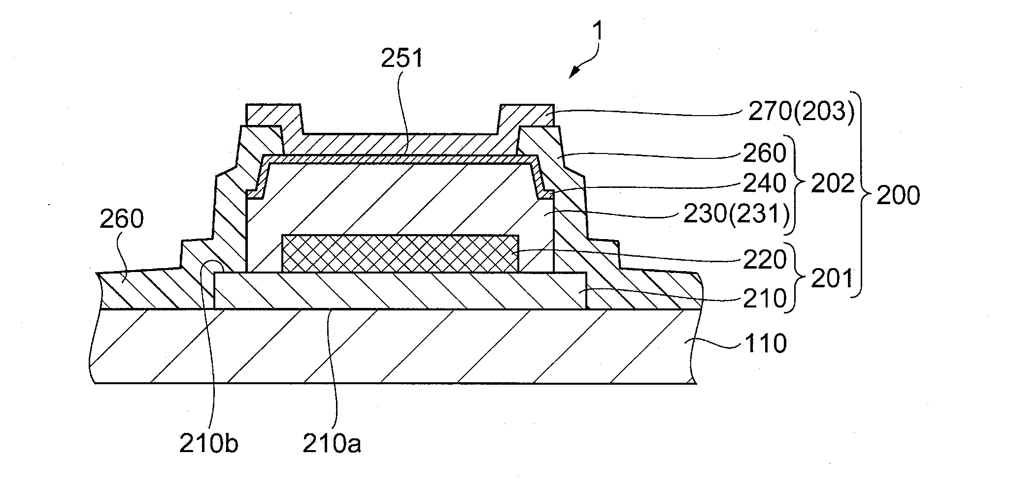
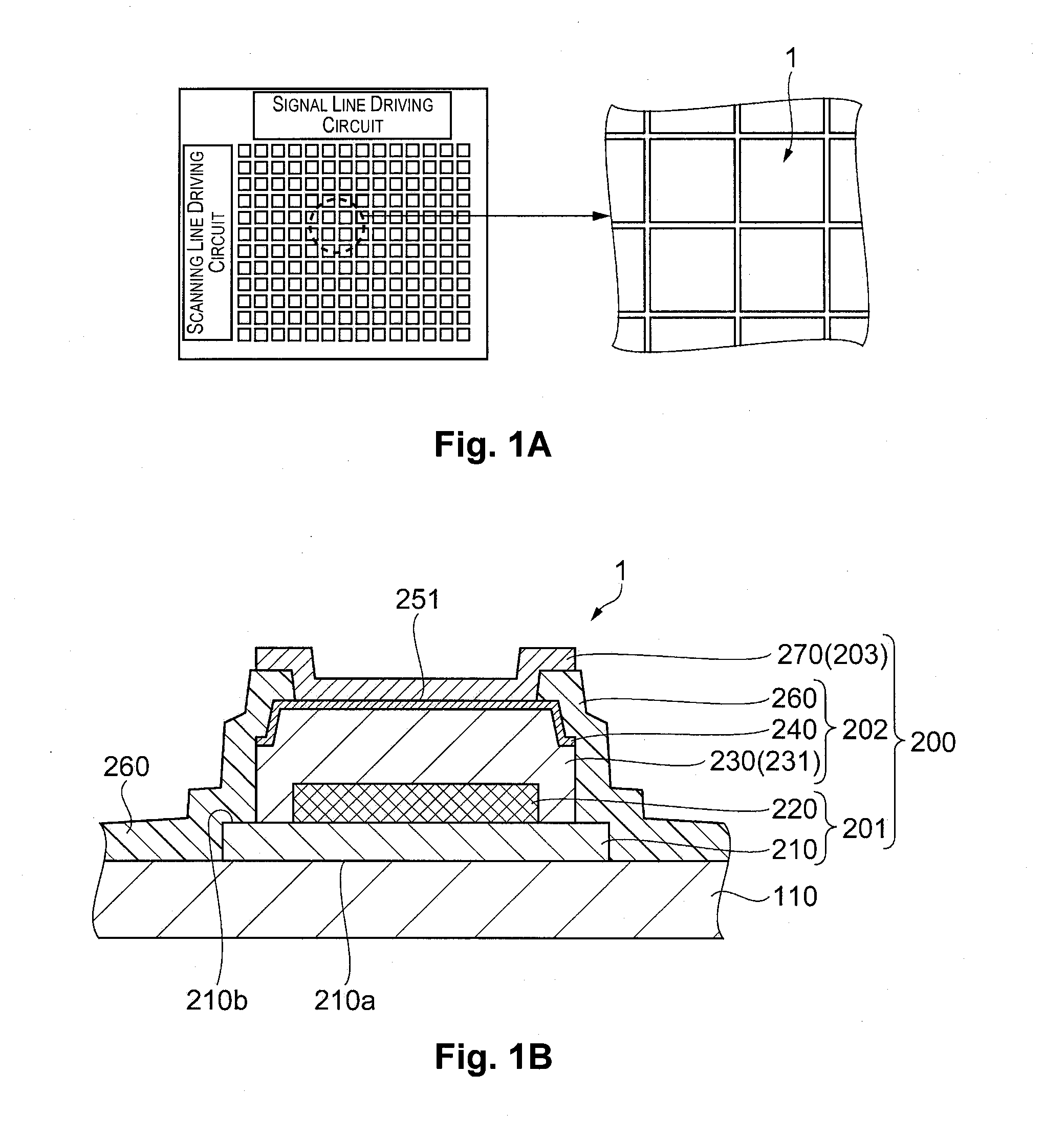
[0029]A photoelectric conversion element and a method of manufacturing a photoelectric conversion element according to the first embodiment will be described using FIG. 1 to FIG. 5.

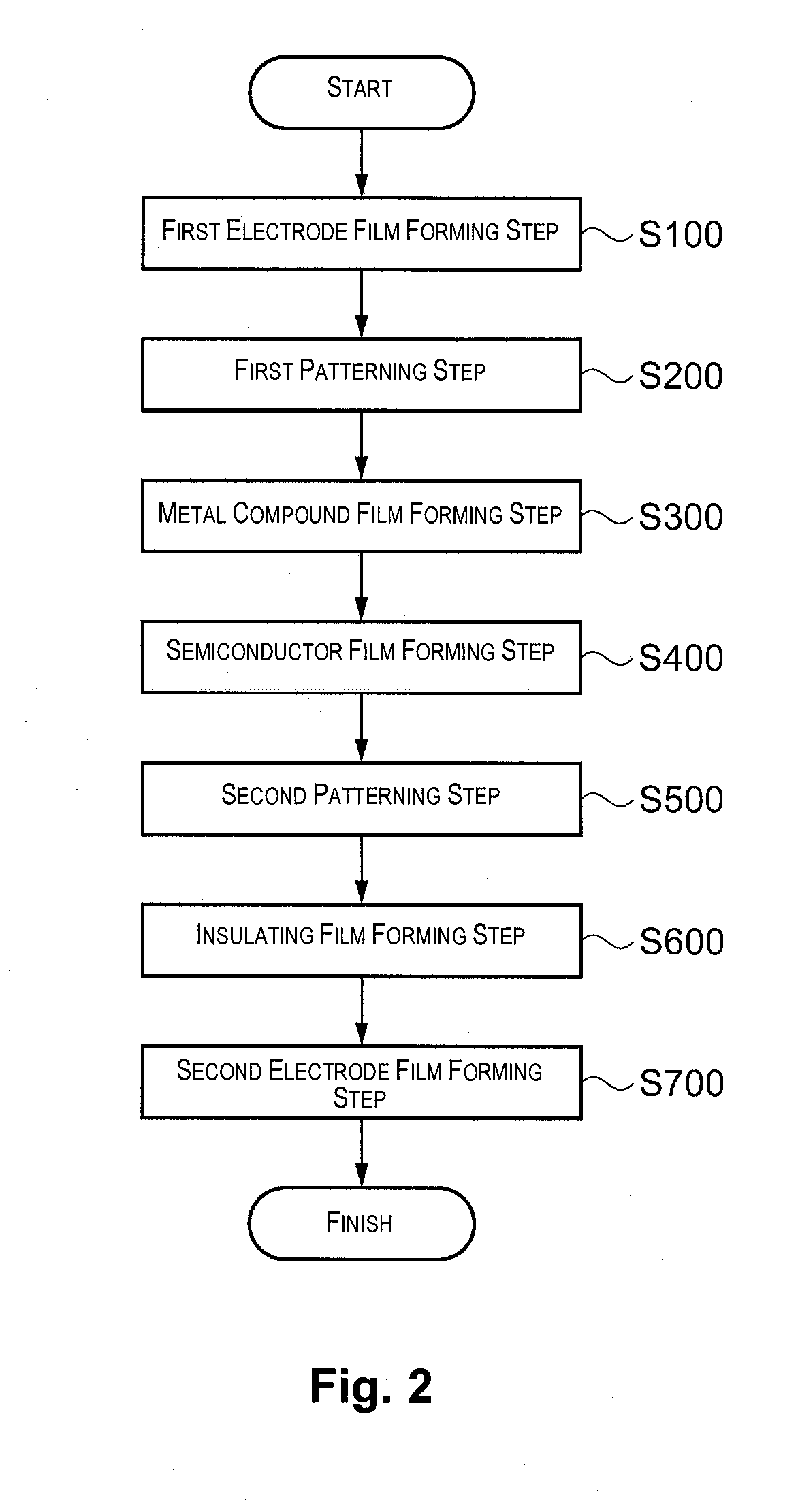
[0030]FIGS. 1A and 1B are diagrams illustrating a schematic configuration of the photoelectric conversion element according to the present embodiment. FIG. 2 is a diagram illustrating a flow of steps where the photoelectric conversion element is manufactured. In addition, FIG. 3 to FIG. 5 are diagrams illustrating steps of manufacturing the photoelectric conversion element. Here, the photoelectric conversion element of the present embodiment is, for example, provided in an array shape on a substrate as shown in FIG. 1A and the photoelectric conversion elements shown in each of the diagrams are shown as cross sections where a portion is enlarged.

Structure of Photoelectric Conversion Element

[0031]A photoelectric conversion element 1 shown in FIG. 1B is provided with a substrate 110 and a photoelectric conve...

second embodiment

[0089]FIG. 6 is a diagram schematically illustrating a schematic configuration of a photoelectric conversion element according to the present embodiment.

[0090]A photoelectric conversion element 2 of the present embodiment is the photoelectric conversion element 1 which was described in the first embodiment which is provided with a circuit section 300.

Structure of Photoelectric Conversion Element 2

[0091]The photoelectric conversion element 2 shown in FIG. 6 is provided with the substrate 110, the circuit section 300, and the photoelectric conversion section 200.

[0092]The circuit section 300 is provided with a switching element 310 on the substrate 110. In addition, the circuit section 300 is provided with a planarization film 320 which covers the switching element 310.

[0093]The photoelectric conversion section 200 is provided with the first electrode section 201, the light absorbing section 202, and the second electrode section 203 on the planarization film 320 described above.

[0094]...

example

[0104]Next, based on FIG. 7, an example of the electronic device will be described where the photoelectric conversion element 1 according to one embodiment of the present invention is applied.

Electronic Device

[0105]FIG. 7 is a diagram illustrating an outline of an alcohol concentration measuring apparatus 1000 as an electronic device which is provided with the photoelectric conversion element 1 according to an embodiment of the present invention. The alcohol concentration measuring apparatus 1000 shown in FIG. 7 is an apparatus which measures the alcohol concentration in blood by irradiating light onto the blood which is flowing through veins and receiving the light which is reflected with the photoelectric conversion element 1.

[0106]The alcohol concentration measuring apparatus 1000 is provided with an imaging apparatus 1120 which irradiates light onto a finger 1200 and receives the light which is reflected, and a control apparatus 1140.

[0107]The imaging apparatus 1120 is provided ...


PUM


Abstract

A method of manufacturing a photoelectric conversion element, which is provided with a substrate, a first electrode film having first and second conductive films provided on the substrate, a metal compound film covering the first electrode film, a semiconductor film connected with the metal compound film, a second electrode film connected with the semiconductor film, and an insulating film covering and surrounding the substrate, the first electrode film, the semiconductor film, and the metal compound film, the method including: forming the first conductive film to be connected with the substrate and the second conductive film to be connected with the first electrode film; forming the second conductive film in a predetermined shape using wet etching after the forming of the first and second conductive films, and forming the metal compound film which covers the first electrode film after the forming of the metal compound film.

Description

CROSS-REFERENCE TO RELATED APPLICATIONS[0001]This application claims priority to Japanese Patent Application No. 2012-206654 filed on Sep. 20, 2012. The entire disclosure of Japanese Patent Application No. 2012-206654 is hereby incorporated herein by reference.BACKGROUND[0002]1. Technical Field[0003]The present invention relates to a photoelectric conversion element, a method of manufacturing a photoelectric conversion element, and an electronic device.[0004]2. Related Art[0005]So-called CIS thin films which include copper (Cu), indium (In), and selenium (Se) and so-called CIGS thin films which include copper (Cu), indium (In), gallium (Ga), selenium (Se), and the like are known as thin films which form semiconductor devices which have a chalcopyrite structure. The CIS and CIGS thin films are frequently used in solar batteries since the photoelectric conversion rate is excellent. In addition, application of the CIS and CIGS thin films to sensors and the like as photoelectric convers...

Claims


Application Information

Patent Timeline
IPC IPC(8): H01L31/0248H01L31/18
CPCH01L31/18H01L31/0248H01L31/022408H01L31/109H01L31/0322H01L31/03923H01L27/1446H01L27/14678A61B5/1455A61B5/4845Y02E10/541Y02P70/50H01L31/0216H01L31/0224H01L31/032H01L31/09H01L31/186
Inventor MIYATA, TAKASHIHATTORI, YASUNORI
Owner SEIKO EPSON CORP
Learn More