
High resolution millimeter wave digitally controlled oscillator with reconfigurable distributed metal capacitor passive resonators

a metal capacitor and high-resolution technology, applied in the field of high-resolution millimeter wave digitally controlled oscillators with reconfigurable distributed metal capacitor passive resonators, can solve the problems of low frequency tuning step less than 1 mhz, poor frequency resolution, and still rely on analog-intensive pll architectures, etc., to achieve fine frequency resolution and tune the range

Inactive Publication Date: 2014-03-27
TECH UNIV DELFT
View PDF5 Cites 21 Cited by
  • Summary
  • Abstract
  • Description
  • Claims
  • Application Information

AI Technical Summary

Benefits of technology

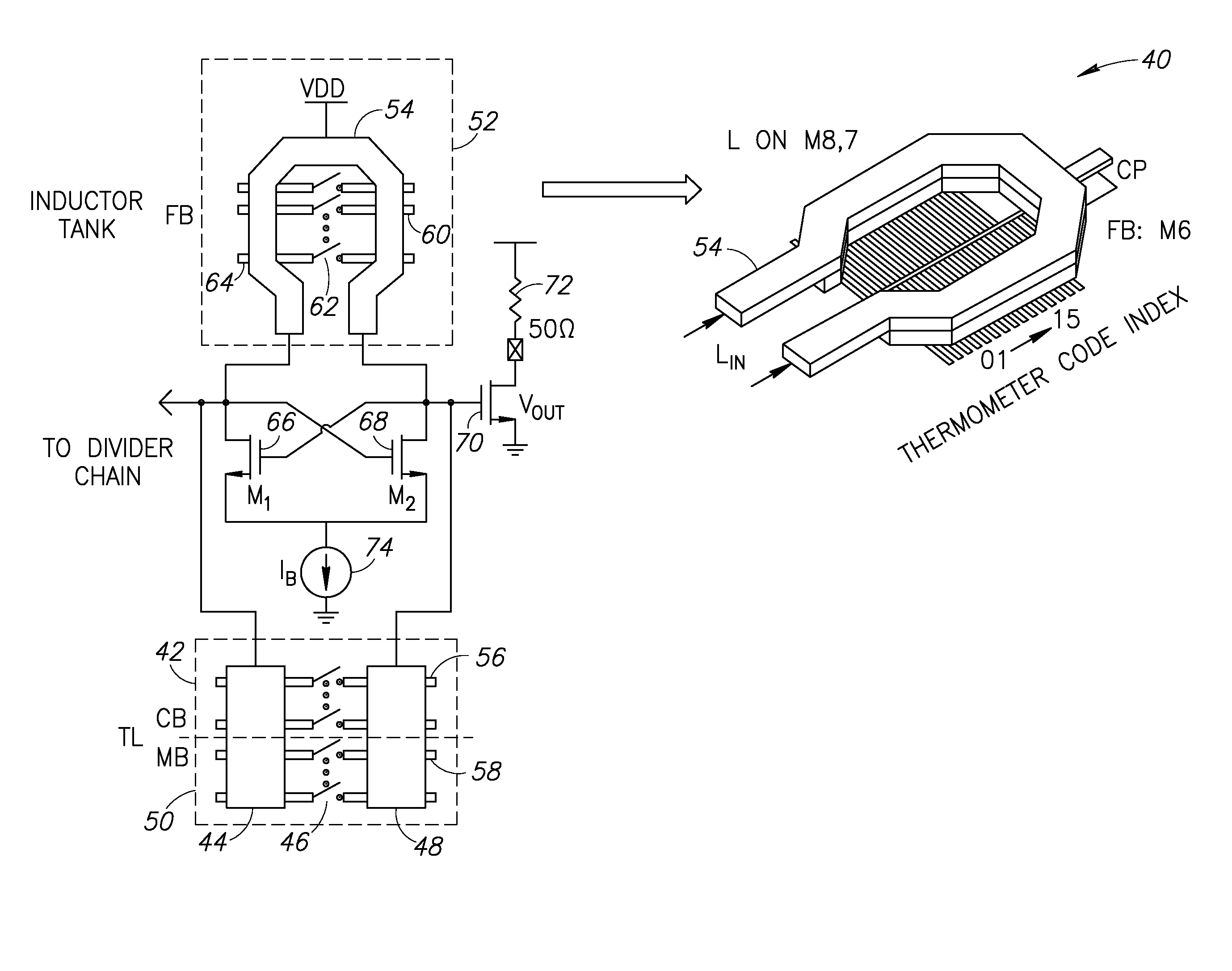
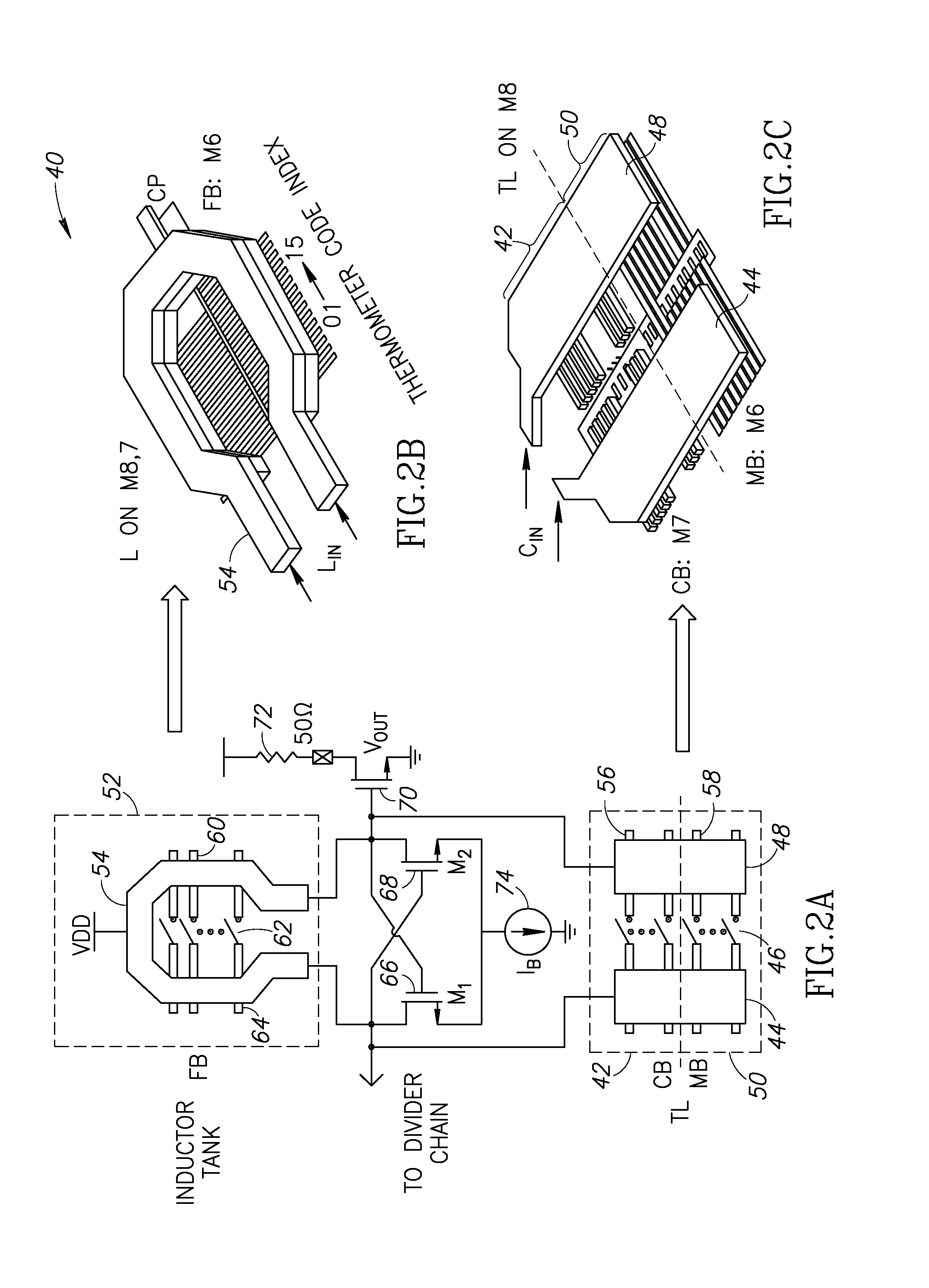
This patent is about a new kind of millimeter-wave digitally controlled oscillator (DCO) that can tune its frequency with a great range of 10% and very fine resolution of less than 1 MHz. The DCO uses a passive resonator with distributed switched metal capacitors or a transformer with switched parallel metal strips to tune its frequency. The DCO has very low phase noise and low power consumption. The circuit measures just 0.4×0.4 mm2 in size. This patent provides an innovative solution for generating millimeter-wave signals at high accuracy and efficiency.

Problems solved by technology

Moreover, a frequency tuning step lower than 1 MHz also cannot be achieved using varactor tuning.
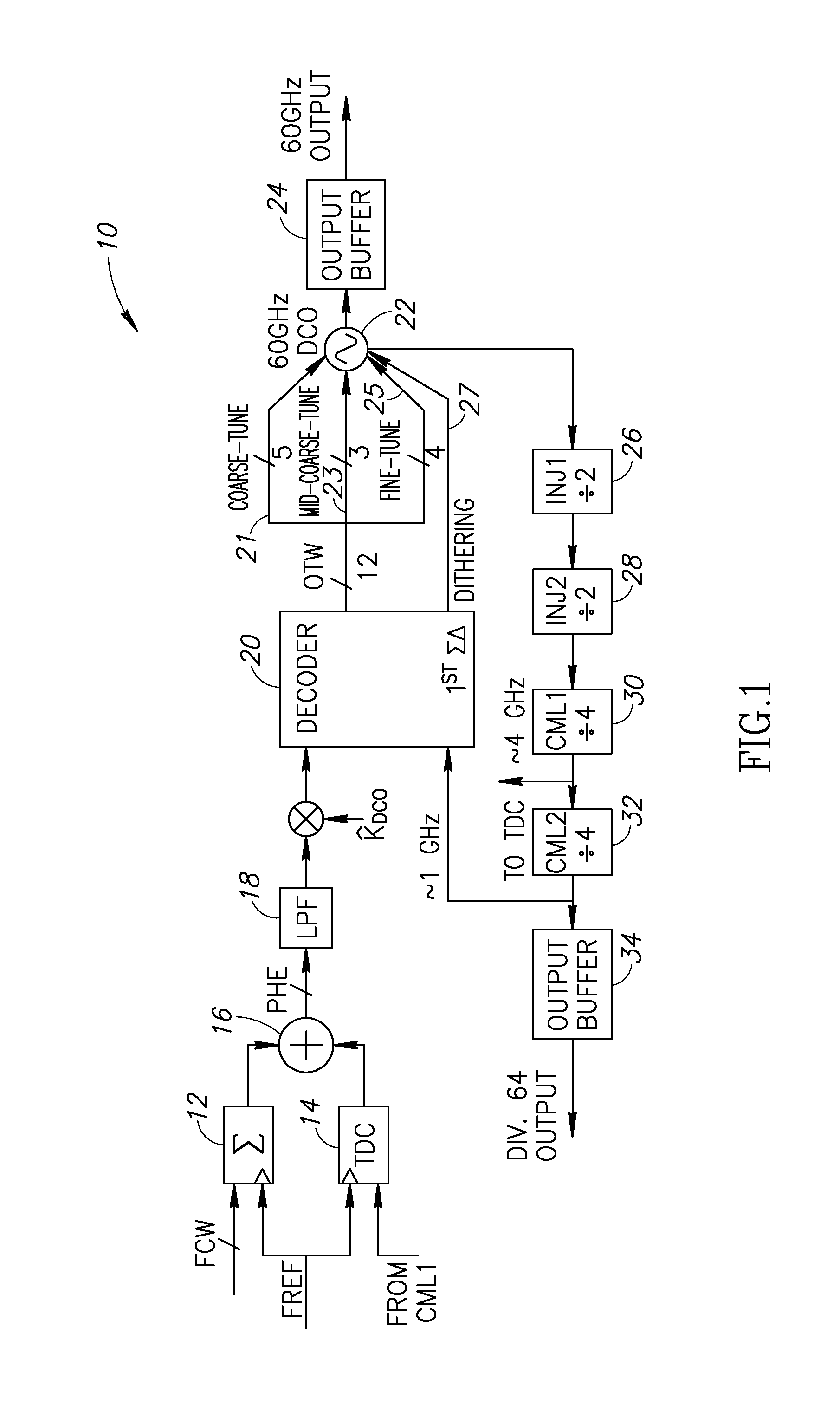
Synthesizers at mm-wave frequencies, however, still rely upon analog-intensive PLL architectures due to the poor frequency resolution of conventional digital controlled oscillators (DCOs) tuned using switched MOS varactors.
Furthermore, the Q-factor is as low as 5 for a 50-fF varactor at 60 GHz which severely affects the phase noise and jitter of a mm-wave DCO.
No prior art DCO operating above 50 GHz has been reported to date that has achieved 10% tuning range and sub-MHz tuning steps simultaneously.

Method used


Image

  • High resolution millimeter wave digitally controlled oscillator with reconfigurable distributed metal capacitor passive resonators
  • High resolution millimeter wave digitally controlled oscillator with reconfigurable distributed metal capacitor passive resonators
  • High resolution millimeter wave digitally controlled oscillator with reconfigurable distributed metal capacitor passive resonators

Examples


Embodiment Construction

[0037]In an example DCO suitable for low-gigahertz oscillation, wide and precise linear frequency tuning is achieved through digital control of a large array of MOS capacitors that operate in the flat region of the C-V curve. The varactors are partitioned into binary-weighted and unit-weighted banks. The tank Q-factor is dominated by the on-chip inductor Q because the varactor banks typically have a Q-factor over 100 when operating below 10 GHz.

[0038]The Q-factor of the oscillator tank and its tuning range, however, are determined primarily by the capacitive tuning elements rather than the inductor at mm-wave frequencies. Considering a phase noise (PN) analysis in the 1 / f2 regime, it is estimated that a tank Q-factor better than 10 is required in order to realize an LC oscillator with PN of −90 dBc / Hz at 1 MHz offset from a 60 GHz carrier (tank C=70 fF, differential oscillation swing ATank=2 V, N=2 for differential circuit, excess noise coefficient γ=2, at room temperature 300 K). A...


PUM


Abstract

A novel and useful millimeter-wave digitally controlled oscillator (DCO) that achieve a tuning range greater than 10% and fine frequency resolution less than 1 MHz. Switched metal capacitors are distributed across a passive resonator for tuning the oscillation frequency. To obtain sub-MHz frequency resolution, tuning step attenuation techniques are used that exploit an inductor and a transformer. A 60-GHz fine-resolution inductor-based DCO (L-DCO) and a 60 GHz transformer-coupled DCO (T-DCO), both fabricated in 90 nm CMOS, are disclosed. The phase noise of both DCOs is lower than −90.5 dBc / Hz at 1 MHz offset across 56 to 62 GHz frequency range. The T-DCO achieves a fine frequency tuning step of 2.5 MHz, whereas the L-DCO tuning step is over one order of magnitude finer at 160 kHz.

Description

REFERENCE TO PRIORITY APPLICATIONS[0001]This application claims priority to U.S. Provisional Application Ser. No. 61 / 701,690, filed Sep. 16, 2012, entitled “Digitally Intensive Transceiver,” U.S. Provisional Application Ser. No. 61 / 701,695, filed Sep. 16, 2012, entitled “Class-F Oscillator,” U.S. Provisional Application Ser. No. 61 / 704,522, filed Sep. 23, 2012, entitled “RF Transceiver,” and U.S. Provisional Application Ser. No. 61 / 829,976, filed May 31, 2013, entitled “Time Domain RF Signal Processing,” all of which are incorporated herein by reference in their entirety.FIELD OF THE INVENTION[0002]The present invention relates to the field of semiconductor integrated circuits and more particularly relates to a high resolution millimeter wave DCO incorporating reconfigurable distributed metal capacitor passive resonators.BACKGROUND OF THE INVENTION[0003]Frequency-modulated continuous-wave (FMCW) radar sensors operating in the millimeter-wave (mm-wave) regime offer fine-resolution ob...

Claims


Application Information

Patent Timeline
Patent Type & Authority Applications(United States)
IPC IPC(8): H03L7/00
CPCH03L7/00H03B5/1228H03B5/1296H03B5/1215H03B5/124H03L7/099H03B5/1218H03B7/06H03B1/00H04B1/10H04B1/26H03H19/002
Inventor WU, WANGHUALONG, JOHN ROBERTSTASZEWSKI, ROBERT BOGDAN
Owner TECH UNIV DELFT
Learn More