Variable frequency converter and adjusting method for the same

a variable frequency converter and adjusting method technology, applied in the field of switch power field, can solve the problems of increasing cost, difficult to add a frequency jitter to relative complexity of the control of the variable frequency converter, so as to achieve the effect of effectively reducing or avoiding the use of emi filters, expanding the operating frequency range and improving the efficiency of the vf converter

Inactive Publication Date: 2014-03-27
DELTA ELECTRONICS SHANGHAI CO LTD
View PDF9 Cites 40 Cited by
  • Summary
  • Abstract
  • Description
  • Claims
  • Application Information

AI Technical Summary

Benefits of technology

[0015]A third aspect of the present application discloses an adjusting method for a VF converter, the VF converter comprises a power stage circuit module and a variable frequency signal stage circuit module which are connected each other to form a closed-loop circuit system. The adjusting method comprises: providing an adjusting unit to the VF converter, loading a continuous interfering signal into a signal inputted to the power stage circuit module by the variable frequency signal sta

Problems solved by technology

Whether it is in switch power or in integrated circuit or other electronic fields, how to effectively decrease EMI is a problem which should be considered in designing a circuit or a system by an electronic designer.
Similarly to the constant frequency converter, the variable frequency converter also has a problem of EMI, an operating frequency of the variable frequency converter will change with change in input or/and output, it is relatively comp

Method used


Image

  • Variable frequency converter and adjusting method for the same
  • Variable frequency converter and adjusting method for the same
  • Variable frequency converter and adjusting method for the same

Examples


embodiment 1

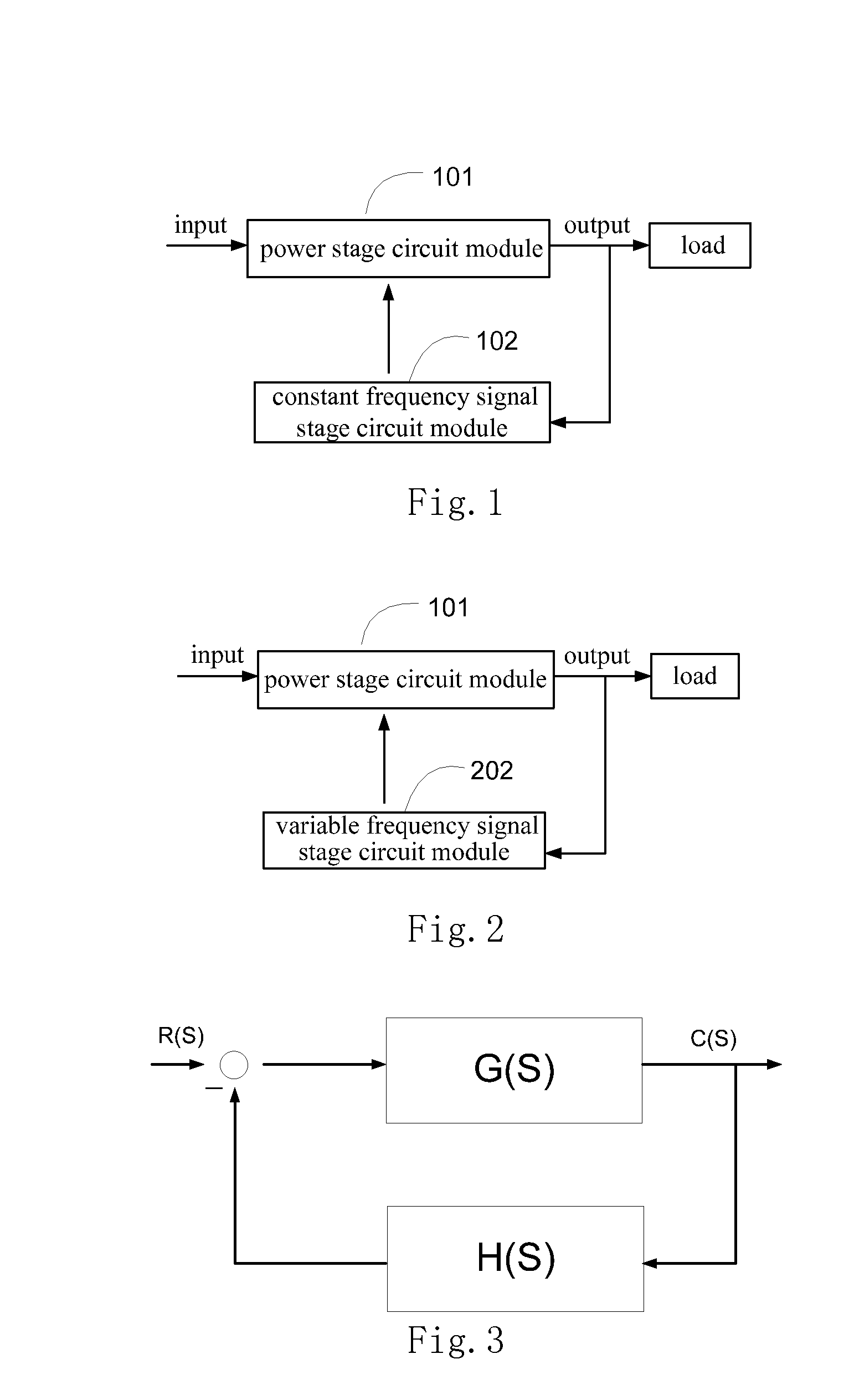
[0047]In the VF converter, if a control signal in the variable frequency signal stage circuit module is continuously changed; operating frequency of the power stage circuit module may be caused to change continuously. If the frequency of continuous interfering signal is higher than a crossover frequency of a VF converter, the continuous interfering signal loaded into the variable frequency signal stage circuit module could make operating frequency of the power stage circuit module change continuously, thereby causing the operating frequency of the VF converter to jitter.

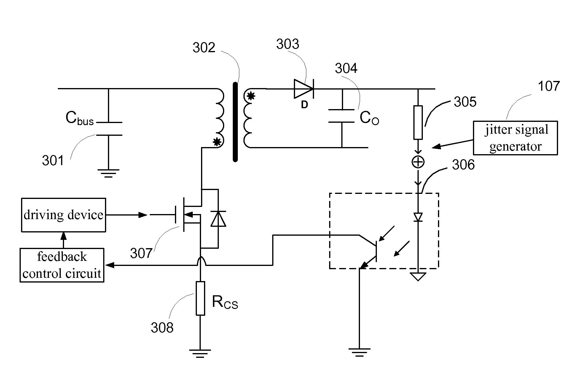
[0048]In FIG. 11, a schematic diagram of the VF converter is illustrated. Wherein, an adjusting unit is implemented by a jitter signal generator 107. The jitter signal generator 107 outputs a continuous interfering signal to the variable frequency signal stage circuit module 202. The jitter signal generator 107 may be a signal generator commonly used in the prior art. The continuous interfering signal is loaded into ...

embodiment 2

[0049]On a basis of the technical solution of FIG. 11, more specifically, the present application discloses another embodiment with reference to FIG. 12.

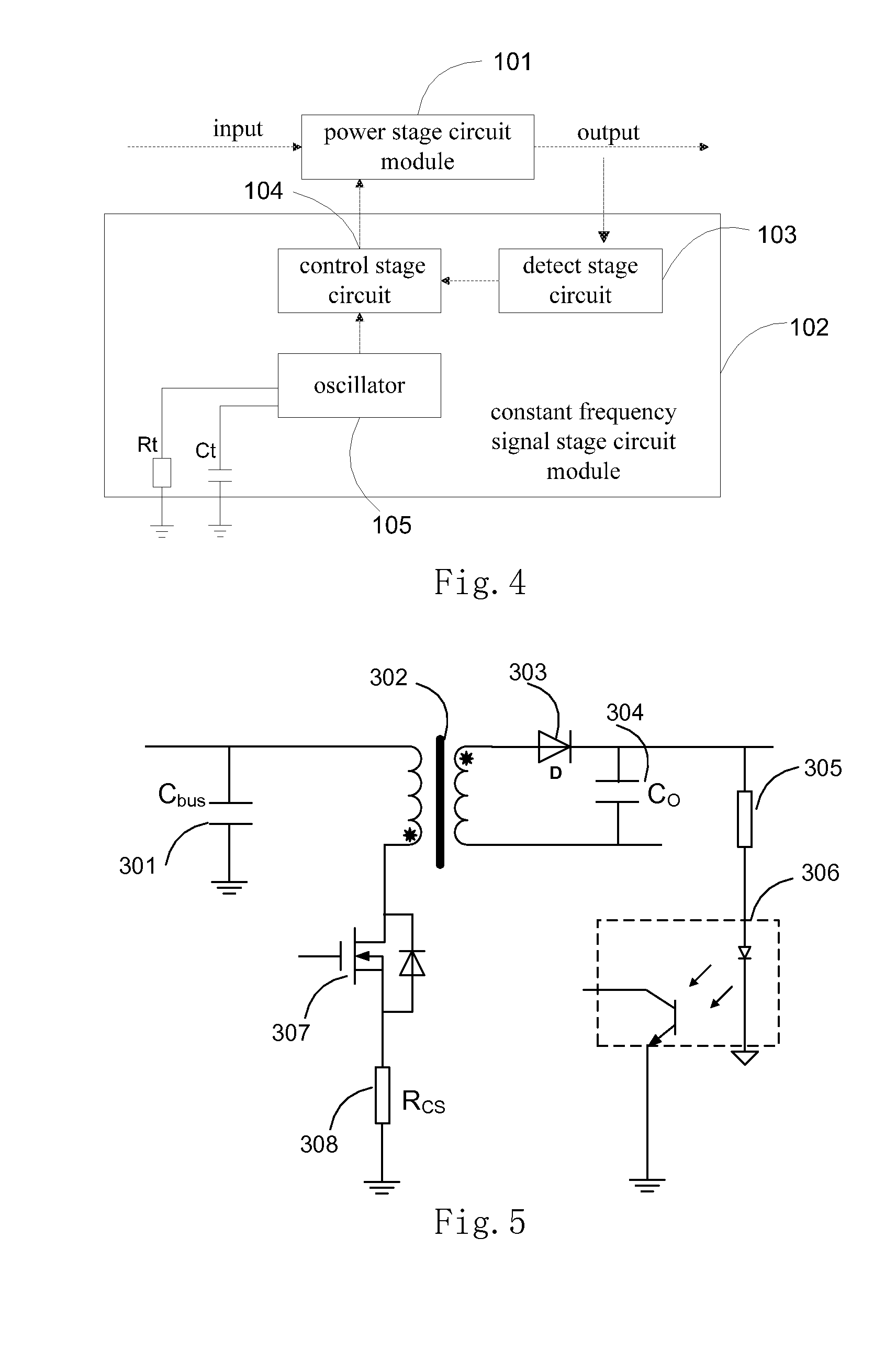
[0050]The variable frequency signal stage circuit module 202 comprises a detection stage circuit and a control stage circuit. Taking a topological graph of a flyback VF converter shown in FIG. 13 as an example, wherein, a power stage circuit module 101 comprises an electrolytic capacitor Cbus 301, a transformer 302, a rectifier diode D303, an output electrolytic capacitor C0 304, and a power switch 307. The detection stage circuit comprises a detecting resistor Rcs 308, a resistor 305, and an optocoupler 306. The detecting resistor Rcs 308 is used for detecting sampling current. Wherein, the detecting resistor Rcs 308 belongs to an input detection stage circuit, the resistor 305 and the optocoupler 306 belong to an output detection stage circuit, and the output detection stage circuit detects output of the power stage circuit module...

embodiment 3

[0056]Similar to FIG. 13, referring to FIG. 16, the present application further discloses another embodiment. FIG. 13 directly changes magnitude of the sampling current detected by input detection stage circuit so as to realize continuous jitter on the operating frequency. FIG. 16 illustrates an embodiment of the present application that a continuous interfering signal generated by an adjusting unit is loaded into an output detection stage circuit. Specifically, in the embodiment illustrated in FIG. 16, the embodiment, that magnitude of a voltage detection signal in an output detection stage circuit is changed so as to realize jitter of the operating frequency on the VF converter, is illustrated.

[0057]The variable frequency signal stage circuit module comprises a detection stage circuit and a control stage circuit. Wherein, a power stage circuit module comprises an electrolytic capacitor Cbus 301, a transformer 302, a rectifier diode D 303, an output electrolytic capacitor C0 304, a...


PUM


Abstract

A variable frequency converter and an adjusting method for the same are provided in the present application. The variable frequency converter operates in a variable frequency mode, and comprises a power stage circuit module and a variable frequency signal stage circuit module which are connected to form a closed-loop circuit system. The variable frequency converter further comprises an adjusting unit outputting a continuous interfering signal and loading the continuous interfering signal into the variable frequency signal stage circuit module so as to cause operating frequency of the power stage circuit module controlled by the variable frequency signal stage circuit module to change continuously. In the present application, in the variable frequency converter, the EMI peak value is decreased.

Description

CROSS-REFERENCE TO RELATED APPLICATIONS[0001]This non-provisional application claims priority under 35 U.S.C. §119(a) on Patent Application No. 201210134931.1 filed in P.R. China on May 3, 2012, the entire contents of which are hereby incorporated by reference.[0002]Some references, if any, which may include patents, patent applications and various publications, may be cited and discussed in the description of this invention. The citation and / or discussion of such references, if any, is provided merely to clarify the description of the present invention and is not an admission that any such reference is “prior art” to the invention described herein. All references listed, cited and / or discussed in this specification are incorporated herein by reference in their entireties and to the same extent as if each reference was individually incorporated by reference.FIELD OF THE INVENTION[0003]The present application relates to a switch power field, and more specifically to a variable freque...

Claims


Application Information

Patent Timeline
IPC IPC(8): H02M3/335
CPCH02M1/44H02M3/33507
Inventor JIN, HONGYUANGE, TAOHU, PEIQINGZHOU, JINPINGGAN, HONGJIANYING, JIANPING
Owner DELTA ELECTRONICS SHANGHAI CO LTD
Why Eureka
Try Eureka