Microphone with Programmable Frequency Response

a microphone and frequency response technology, applied in the field of capacitor microphones, can solve the problems of loss of signal contents, unsatisfactory distortion, signal clipping, etc., and achieve the effect of effectively removing the impedance and effectively couple the impedan

Active Publication Date: 2014-03-27
INVENSENSE
View PDF4 Cites 78 Cited by
  • Summary
  • Abstract
  • Description
  • Claims
  • Application Information

AI Technical Summary

Benefits of technology

[0018]The second circuit may be configured to effectively remove the impedance from the input of the first circuit in response to automatic detection that the signal from the downstream node does not meet the predetermined

Problems solved by technology

Under these circumstances, the diaphragm may reach its absolute displacement limit, and the resulting signal may therefore be “clipped,” causing undesirable distortion.
Even if the diaphragm does not reach its absolute displacement limit, the ASIC or other processing circuitry may not be able to handle peaks in the electrical signal from the condenser microphone element due to limited voltage available from a power supply, and the signal may, therefo

Method used


Image

  • Microphone with Programmable Frequency Response
  • Microphone with Programmable Frequency Response
  • Microphone with Programmable Frequency Response

Examples


Embodiment Construction

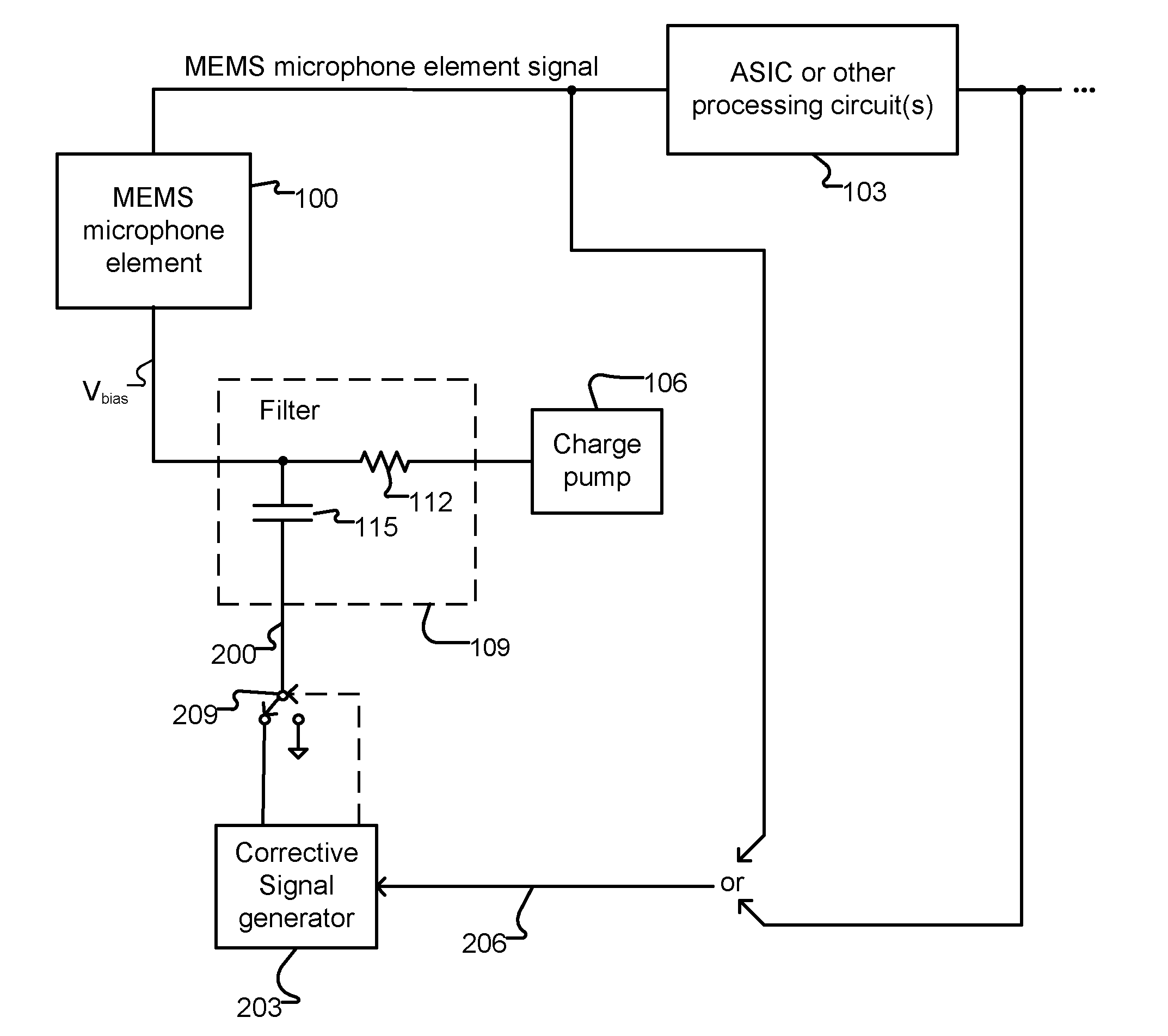
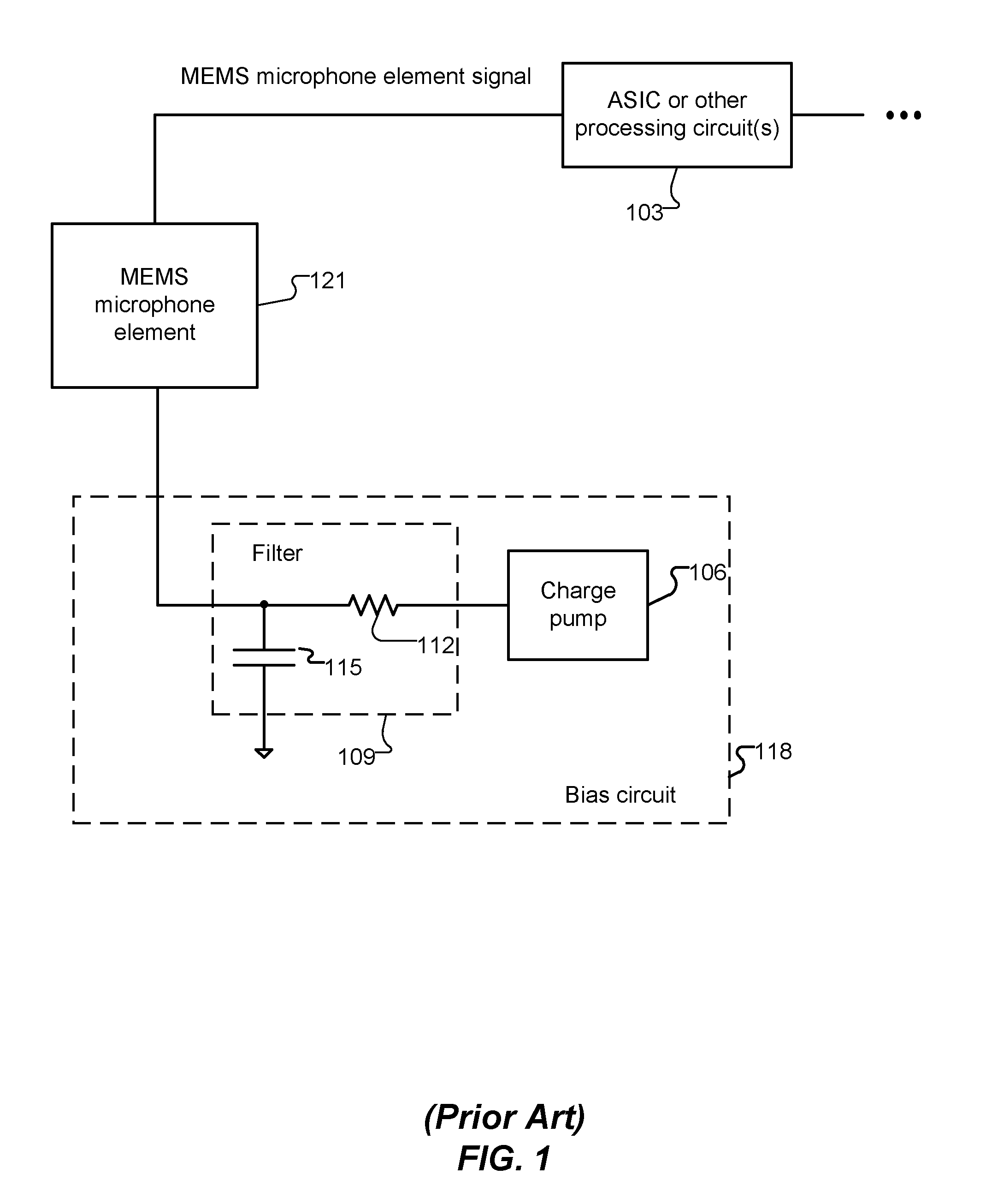
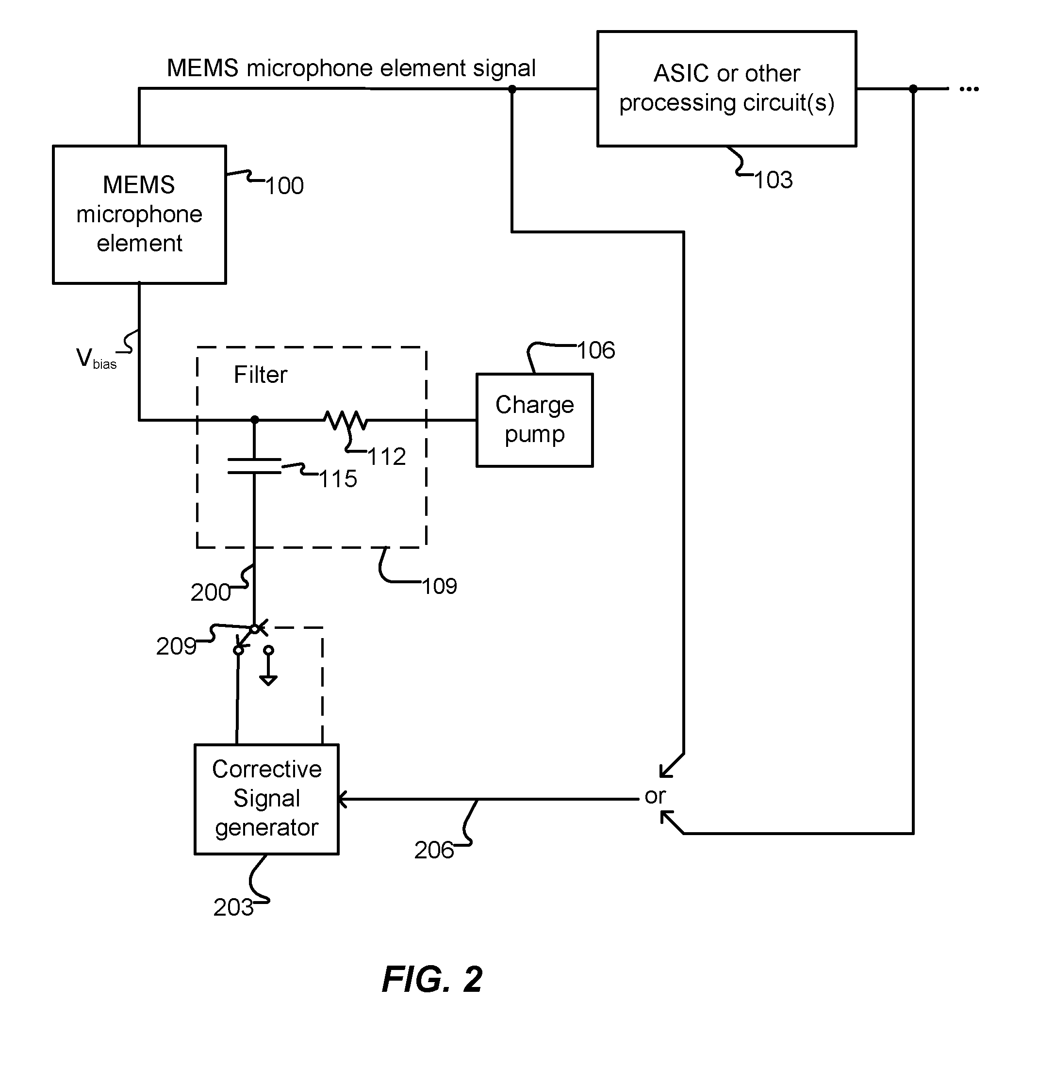
[0009]An embodiment of the present invention provides a microphone system. The microphone system includes a transducer, a first circuit and a second circuit. The transducer includes a vibratable structure configured to establish a capacitance that varies in accordance with an acoustic signal received by the transducer. The first circuit has an input coupled to the transducer to receive, via the input, an electrical signal that varies in accordance with the variable capacitance of the transducer. The first circuit has an output and is configured to process the received electrical signal and provide a corresponding processed electrical signal at the output. The second circuit is coupled to the input of the first circuit and to a node downstream of the output of the first circuit. The second circuit is configured to automatically detect when a signal from the downstream node meets a predetermined criterion and, in response, effectively couple an impedance to the input of the first circ...


PUM


Abstract

Methods and apparatus automatically cancel or attenuate an unwanted signal (such as low frequencies from wind buffets) from, and/or control frequency response of, a condenser microphone, or control the effective condenser microphone sensitivity before the signal reaches an ASIC or other processing circuit. As a result, the maximum amplitude signal seen by the processing circuit is limited, thereby preventing overloading the input of the processing circuit. Remaining (wanted) frequencies can be appropriately amplified to reduce the noise burden on further processing circuits. A corrective signal is applied to a bias terminal of the condenser microphone to cancel the unwanted signal. Optionally or alternatively, a controllable impedance is connected to a line that carries the signal generated by the MEMS microphone, so as to attenuate unwanted portions of the signal.

Description

TECHNICAL FIELD[0001]The present invention relates to capacitor microphones, and more particularly to condenser microphones with programmable frequency response.BACKGROUND ART[0002]Condenser microphones are commonly used in mobile telephones and other consumer electronic devices, embedded systems and other devices. Condenser microphones include microelectromechanical systems (MEMS) microphones, electret condenser microphones (ECMs) and other capacitor-based transducers of acoustic signals. A MEMS microphone element typically includes a conductive micromachined diaphragm that vibrates in response to an acoustic signal. The microphone element also includes a fixed conductive plate parallel to, and spaced apart from, the diaphragm. The diaphragm and the conductive plate collectively form a capacitor. An electrical charge is placed on the capacitor, typically by an associated circuit. The capacitance of the capacitor varies rapidly as the distance between the diaphragm and the plate var...

Claims


Application Information

Patent Timeline
IPC IPC(8): H03G5/00
CPCH04R3/06H04R3/00H04R19/005H04R19/016H04R19/04H04R2201/003
Inventor JOSEFSSON, OLAFUR MAR
Owner INVENSENSE
Why Eureka
Try Eureka