
Exhaust Gas Diverter and Collection System For Ocean Going Vessels

Active Publication Date: 2014-04-03
ADVANCED CLEANUP TECH +1
View PDF18 Cites 24 Cited by
  • Summary
  • Abstract
  • Description
  • Claims
  • Application Information

AI Technical Summary

Benefits of technology

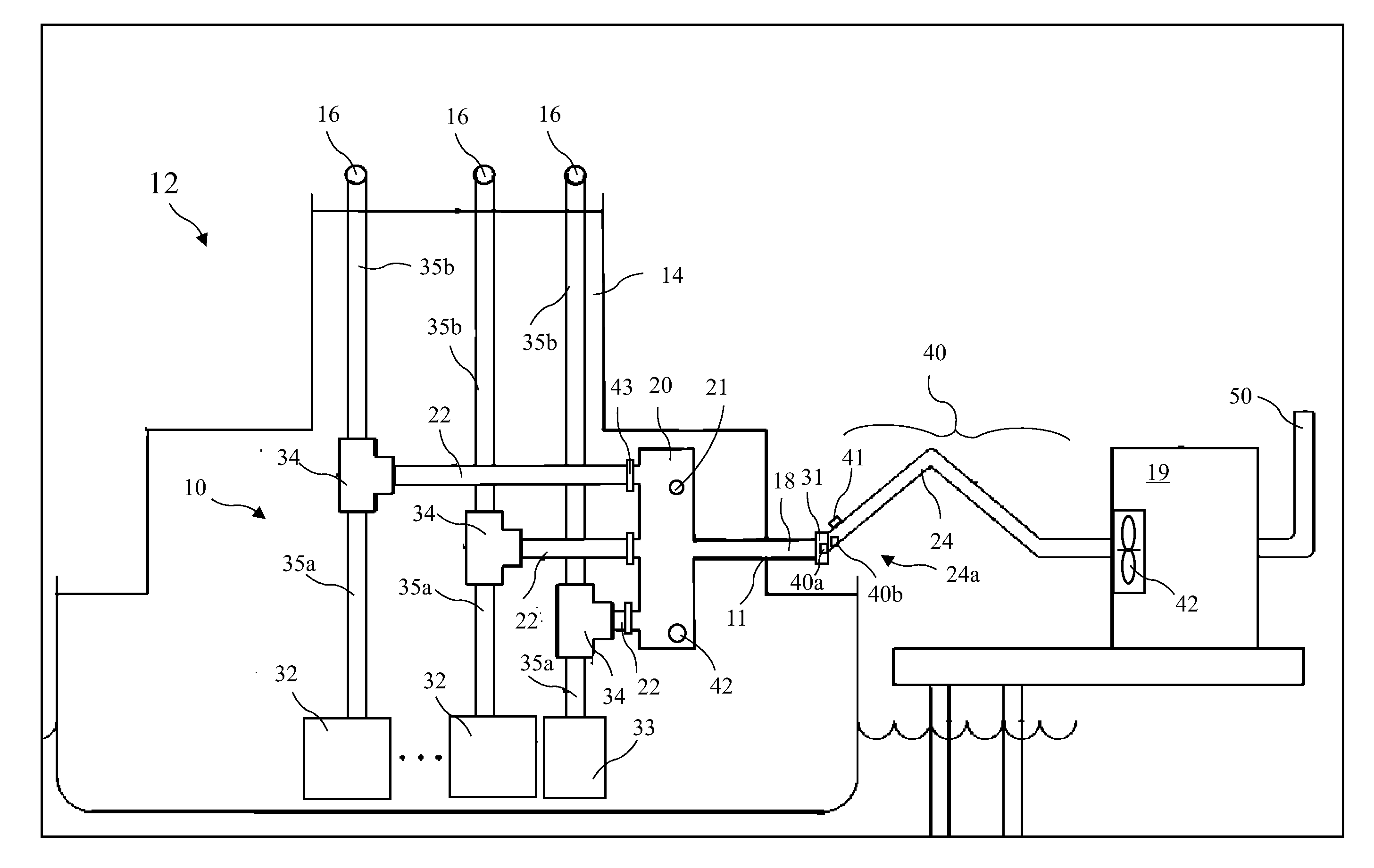
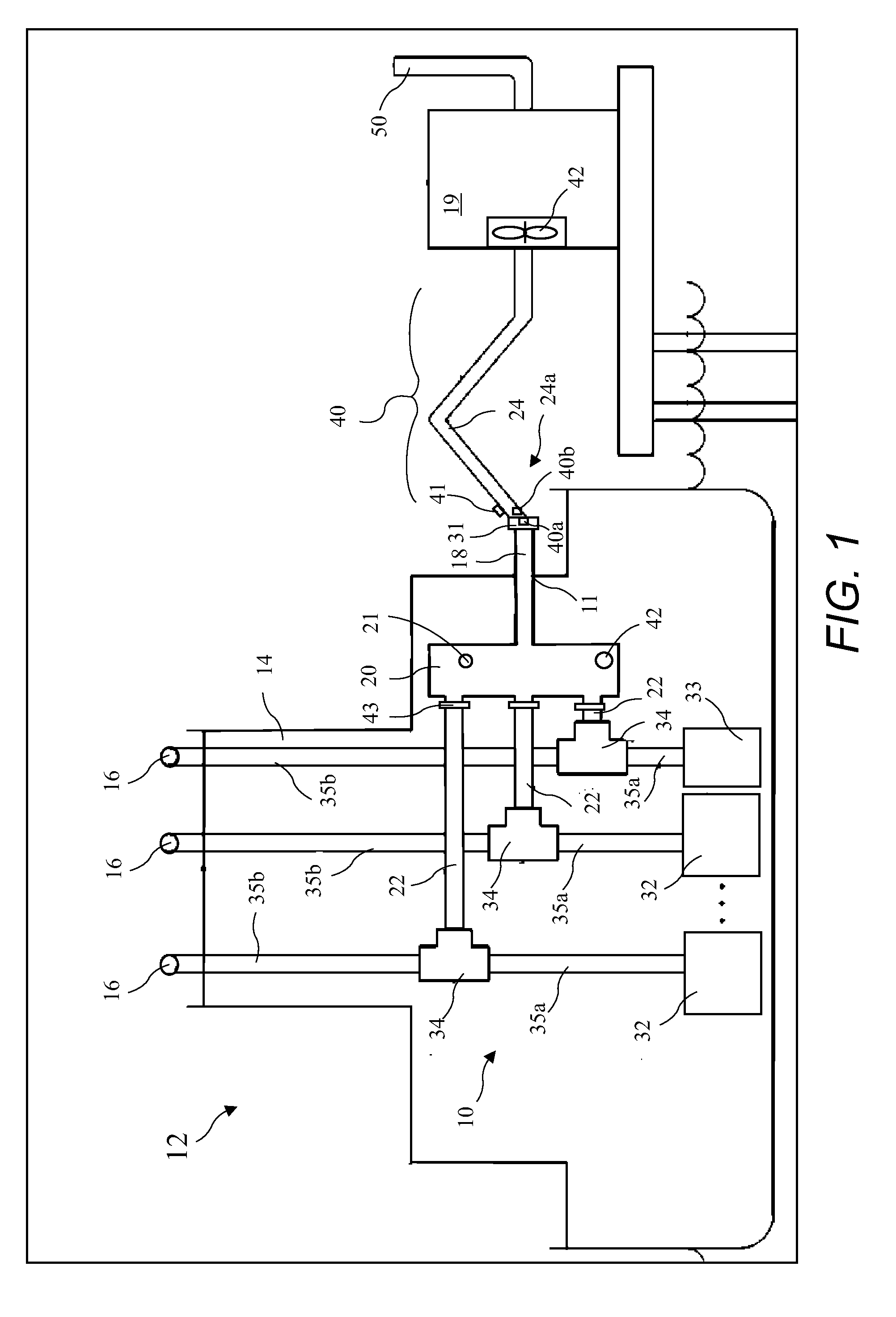
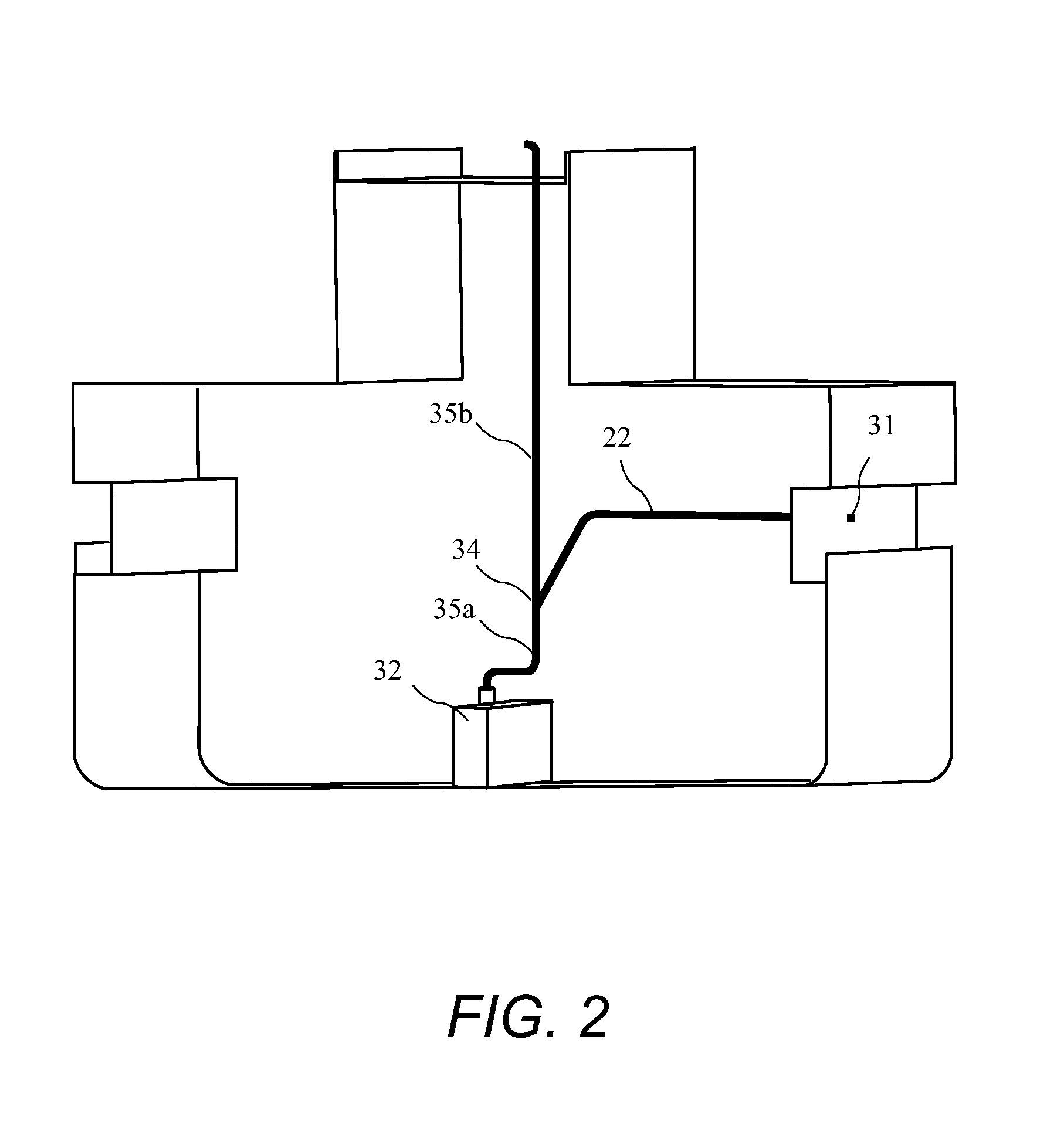
The present invention provides an exhaust gas collection system for a vessel that collects exhaust gas from auxiliary engines and other sources on the vessel. The system redirects the exhaust gas to an emissions treatment system for removal of air pollutants and greenhouse gases. The system includes ducts and couplings to connect the ducts to the external connection system. A jib-type small crane or arm may be used to position the couplings during installation. A standard pressure relief valve is provided to protect the engines and boilers in case of blockage or malfunction. The system also includes automatically actuated valves and covers for each duct. The couplings may perform several functions, including alignment, attachment, and sealing. A positioning system, such as a pivoting arm or crane, may also be provided for easy positioning of the system.

Problems solved by technology

OGVs at berth or anchored in port are a significant source of air pollution from the exhaust gases of their auxiliary power sources.
If allowed to cool, this fuel becomes so viscous it is difficult or impossible to pump.
A tall crane is therefore required to reach the top of the stack, which adds expense, and requires a skilled and certified crane operator.
Another issue with connecting to the top of the stack is that the connection operation is very difficult to carry out by personnel locally at the stack because of dangers of hot exhaust and pipes, toxic fumes, and limited accessibility at best.
This remote operation adds cost and complexity to the operation.
Another issue is higher winds at the top of the stacks which makes the connection more difficult.
A device hanging from a crane, or other placement device, many tens of feet above ground or sea level, and often over 100 feet above ground or sea level, is frequently subjected to wind forces which cause the attachment system to sway with relatively large excursions, creating a danger of hitting and damaging antennas or other nearby OGV structures.
This movement also makes alignment and attachment to the stack difficult if not impossible in windy conditions.
Another drawback is that the exhaust gas must be ducted all the way to the ground, which adds cost and this ducting has to be supported by some means as it makes its way to ground level where the processing equipment is located.
This additional duct length adds cost in material for the duct itself and operating cost due to increased pressure drop.
While the system of the '520 application overcomes some of the difficulties of the '710 patent, there remains a need to connect to the original exhaust pipes which is not always convenient, must be performed at a very high point on the OGV, and requires lengthy ducting.

Method used


Image

  • Exhaust Gas Diverter and Collection System For Ocean Going Vessels
  • Exhaust Gas Diverter and Collection System For Ocean Going Vessels
  • Exhaust Gas Diverter and Collection System For Ocean Going Vessels

Examples


Embodiment Construction

[0025]The following description is of the best mode presently contemplated for carrying out the invention. This description is not to be taken in a limiting sense, but is made merely for the purpose of describing one or more preferred embodiments of the invention. The scope of the invention should be determined with reference to the claims.

[0026]In the following detailed description, the term stack refers to the large structure protruding from the upper part of an Ocean Going Vessel (OGV) and from which exhaust gas may be observed to exit the OGV. An alternative term for stack, used by some in the marine field, is funnel. The stack contains or encompasses several individual OGV exhaust pipes. Each of the OGV exhaust pipes connects to one source of exhaust gas such as one auxiliary engine or one auxiliary boiler or an onboard incinerator. The terms vessel and OGV mean one and the same, namely an OGV used to transport cargo or people, and the terms are used interchangeably in the mari...


PUM

PropertyMeasurementUnit
Pressureaaaaaaaaaa
Flow rateaaaaaaaaaa
Flexibilityaaaaaaaaaa

Abstract

An exhaust gas collection system for capturing the exhaust gas emitted by auxiliary engines, auxiliary boilers and other sources on an Ocean Going Vessel (OGV) while at berth or at anchor, so that these gases may be carried to an emissions treatment system for removal of air pollutants and greenhouse gases. The exhaust gas collection system includes a diverter to redirect the exhaust gas normally carried by exhaust pipes to the OGV's stack for release to the atmosphere, to an exhaust gas treatment system. The emissions treatment system may be land-based, water-based, or on the OGV. When the emissions treatment system is land-based, water-based, the exhaust gas is carried to a connection location that accessible by a ducting system to carry the exhaust gas to the emissions treatment system. The exhaust gas collection system preferably includes parallel-flow ducts and a manifold to combine the parallel-flows into a single duct for more convenient routing through the vessel.

Description

BACKGROUND OF THE INVENTION[0001]The present invention relates to control of emissions from Ocean Going Vessels (OGVs) at berth or anchored in port and in particular to the collection of exhaust gases inside the OGVs to allow subsequent processing.[0002]OGVs at berth or anchored in port are a significant source of air pollution from the exhaust gases of their auxiliary power sources. The OGVs have auxiliary diesel engines and auxiliary boilers which normally remain in operation while the OGV is at berth or anchored. The auxiliary engines drive generators which provide power for ballast and other pumps, onboard motors, shipboard lighting and air conditioning, communications equipment, and other housekeeping functions. The auxiliary boilers are used to keep the bunker fuel used to feed the main engines warm. If allowed to cool, this fuel becomes so viscous it is difficult or impossible to pump. Heat from the boilers is also used for other shipboard functions.[0003]The boilers and auxi...

Claims


Application Information

Patent Timeline
IPC IPC(8): F01N13/08F01N13/10F01N3/00
CPCB63H21/32B63H21/38F01N13/004B08B15/00B01D46/42B63H21/34
Inventor POWELL, JOHNSHARP, ROBERT
Owner ADVANCED CLEANUP TECH
Learn More