
Electric supercharger, assembling method of the same, and internal combustion engine

a technology of electric supercharger and assembling method, which is applied in the direction of machines/engines, manufacturing stator/rotor bodies, liquid fuel engines, etc., can solve the problems of many challenges in durability, assembly and installation ease, and reduce the cost of the configuration of the supercharger , the effect of suppressing the reduction in the output of the rotation sha

Active Publication Date: 2014-04-03
MITSUBISHI HEAVY IND ENGINE & TURBOCHARGER LTD
View PDF3 Cites 50 Cited by
  • Summary
  • Abstract
  • Description
  • Claims
  • Application Information

AI Technical Summary

Benefits of technology

The present invention provides an electric supercharger that reduces vibration and noise in an internal combustion engine. The electric supercharger includes a compressor wheel, an electric motor, a motor inverter, a rolling bearing, a sleeve, and a damper mechanism. The motor inverter controls the rotation speed of the rotating shaft, and the rolling bearing rotatably supports the shaft. The damper mechanism elastically supports the sleeve, which is outside the rolling bearing and forms a gap between the sleeve and the rolling bearing. This significantly reduces vibration and prevents eccentric load, simplifies the supercharger's configuration and reduces costs, while also stabilizing the rolling bearing against thrust force. Additionally, the electric supercharger can be easily assembled and mounted in a compact way, improving fuel efficiency and facilitating mounting to vehicles.

Problems solved by technology

However, the electric supercharger has many challenges in durability, ease of assembly and ease of installation at the time of installation to the vehicle.

Method used


Image

  • Electric supercharger, assembling method of the same, and internal combustion engine
  • Electric supercharger, assembling method of the same, and internal combustion engine
  • Electric supercharger, assembling method of the same, and internal combustion engine

Examples


first embodiment

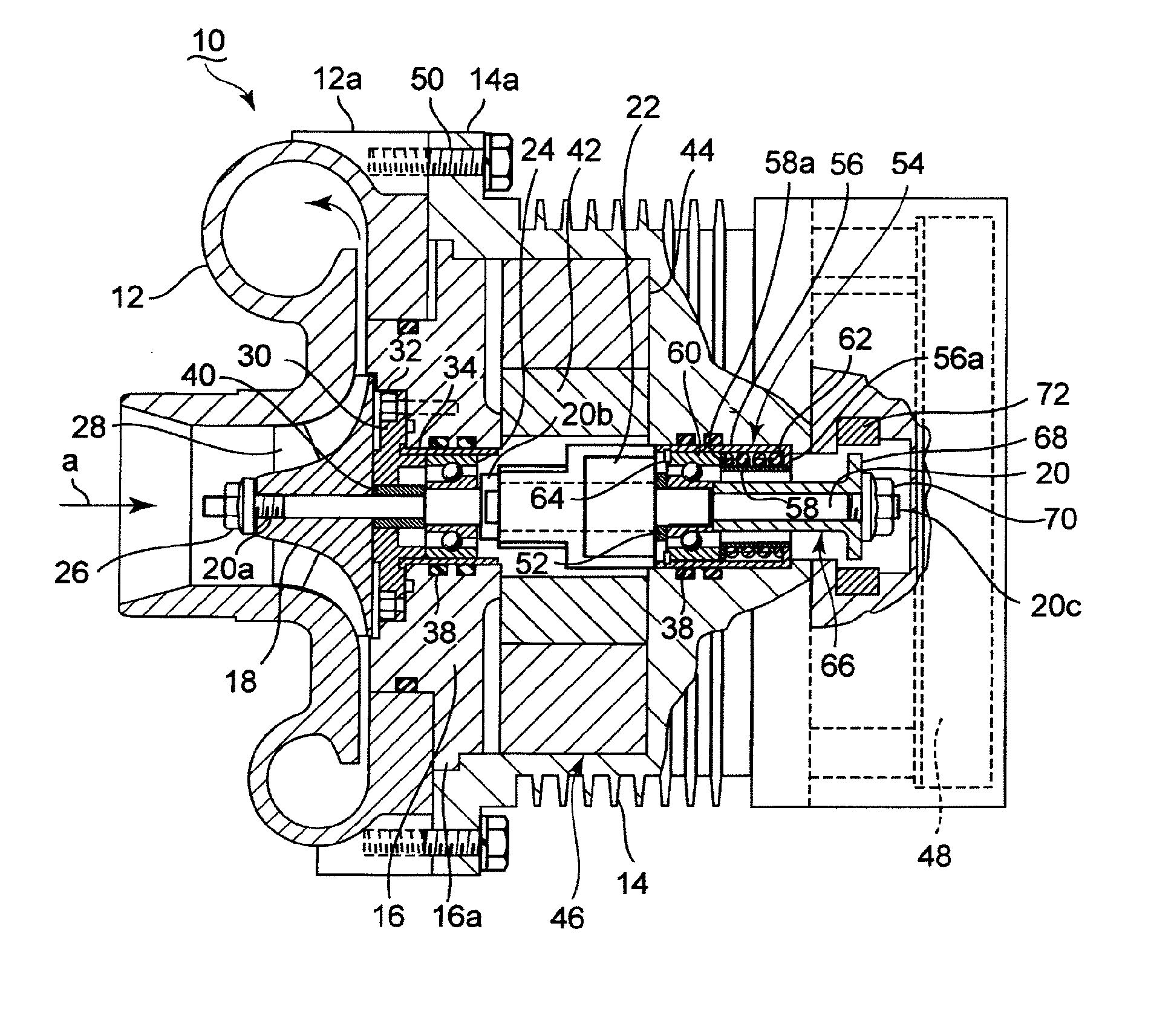
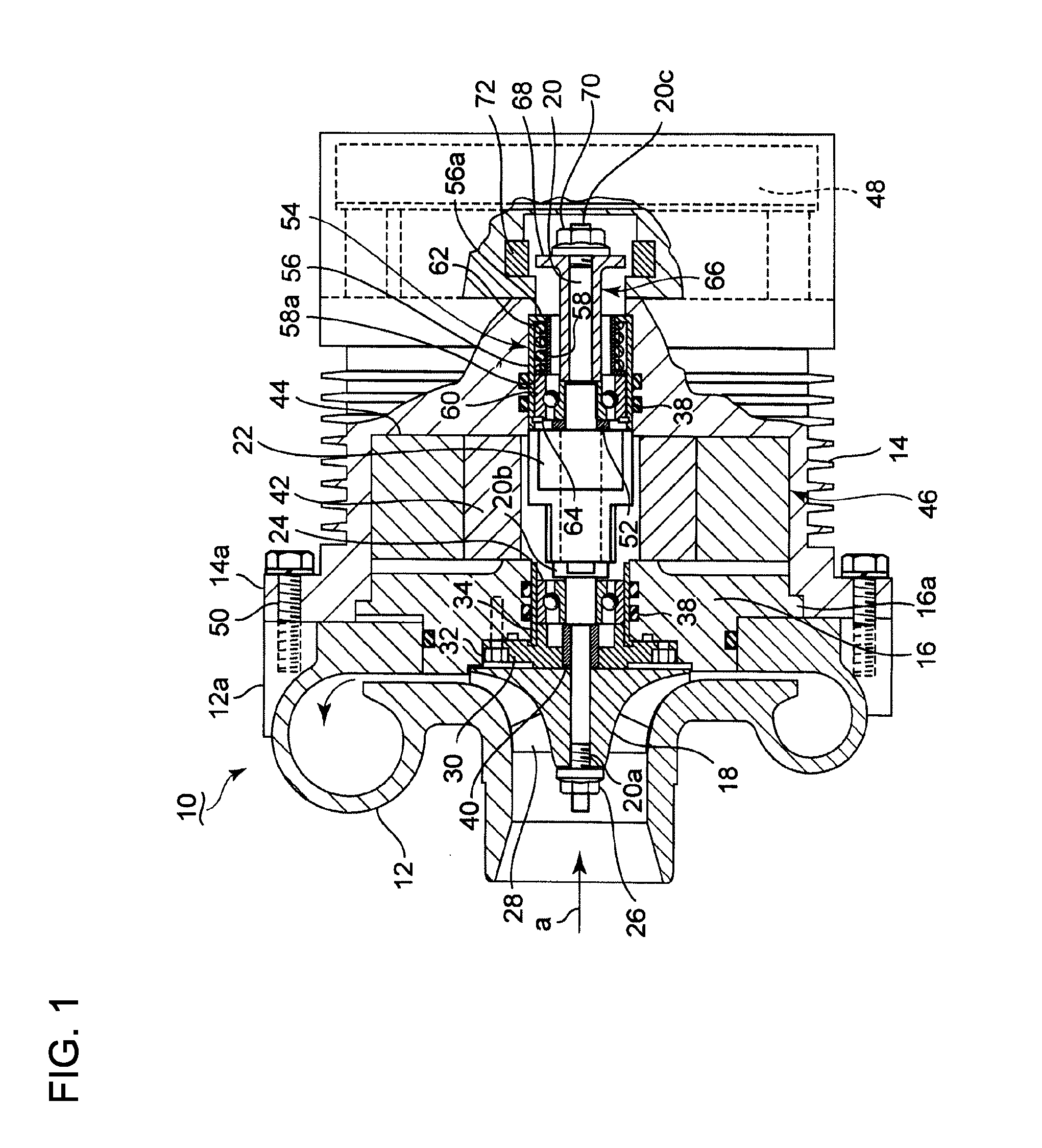
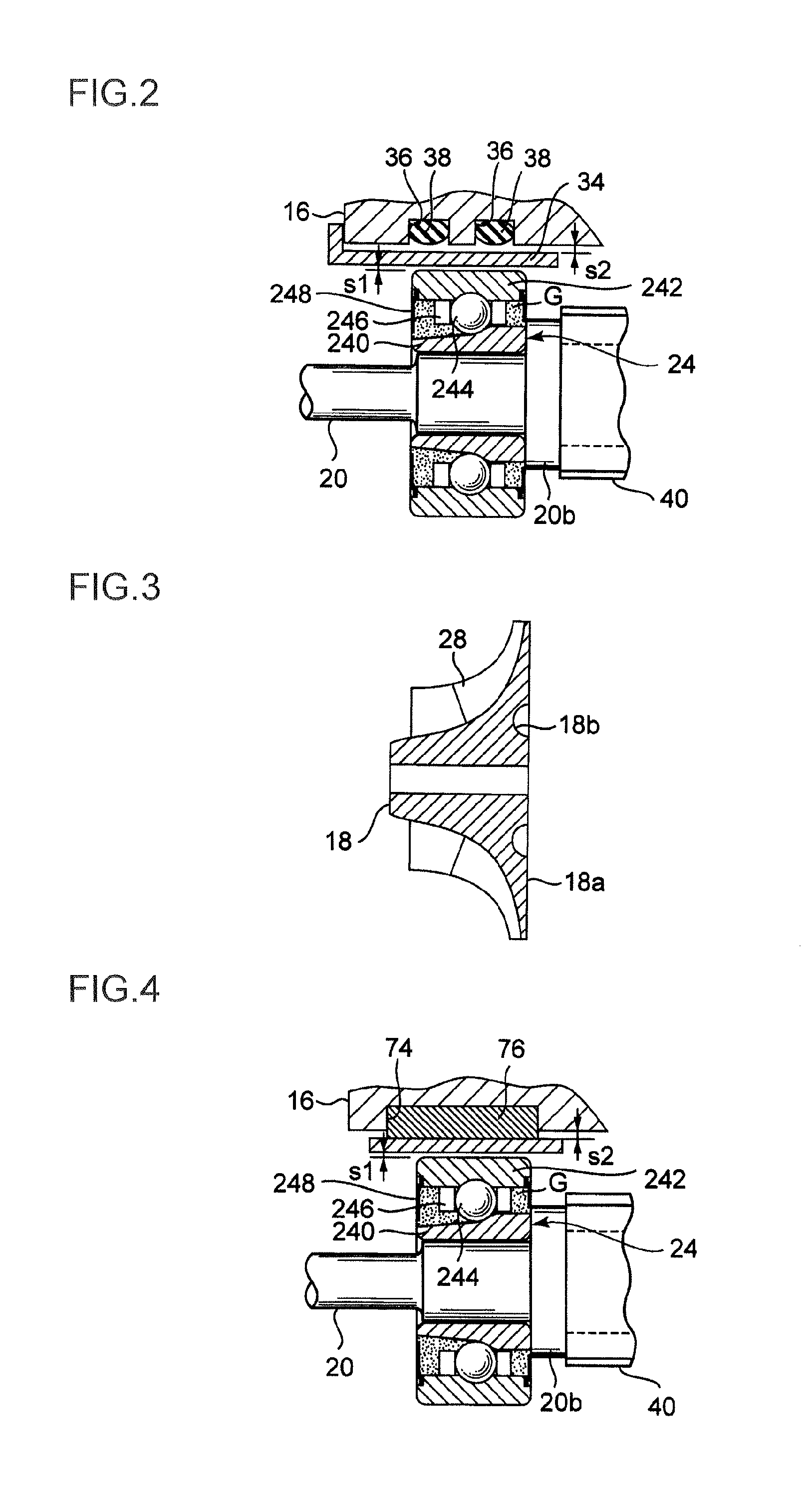
[0040]An electric supercharger according to a first embodiment of the present invention is described in reference to FIG. 1 to FIG. 3. The electric supercharger 10 of this embodiment is provided in an intake passage (not shown) of an internal combustion engine installed in a vehicle. A housing for the electric supercharger 10 is composed of a compressor housing 12, an integrated housing 14 functioning as a housing for an electric motor and a motor inverter, and a bearing housing 16. Inside the compressor housing 12, a compressor wheel 18 is housed. A through-hole is provided on an axial center line of the compressor wheel 18. An end of a rotation shaft 20 is fitted into the through-hole and a nut 26 is screwed to a screw portion 20a formed at the end of the rotation shaft 20 so as to join the compressor-side end of the rotation shaft 20 to the compressor wheel 18. The rotation shaft 20 is arranged on the axial center line of the compressor housing 12.

[0041]A plurality of impellers 2...

second embodiment

[0059]Next, the electric supercharger according to a second embodiment of the present invention is described in reference to FIG. 4. In this embodiment, a groove 74 is provided on the inner surface of the bearing housing 16. The groove 74 has a rectangular cross section with width wider than the groove 36. In the groove 74, a flat rubber damper 76 which is wide and has a rectangular cross section is fitted to the groove 74. The second embodiment is substantially the same as the first embodiment except that the elastic damper 76 is in contact with the sleeve 34, and the gaps s1 and s2 are formed on both sides of the sleeve 34.

[0060]According to this embodiment, in addition to the effects obtained by the first embodiment, by providing one wide groove 74, it facilitates formation of the groove and also by providing the wide elastic damper 76, it enhances the elastic support function of the rotation shaft 20 and further reduces the vibration of the electric motor 46 and the motor invert...

third embodiment

[0062]Next, the electric supercharger according to a third embodiment of the present invention is described in reference to FIG. 5. This embodiment illustrates the exemplary case where a bypass passage is provided in the intake passage of the internal combustion engine, the bypass passage being configured so that the intake air bypasses the compressor wheel 18. The compressor housing 12 has an exhaust port 12b for the supply air a. Further, the bypass passage 78 is integrally formed in the compressor housing 12, and a bypass valve 79 is provided in the bypass passage 78.

[0063]According to this embodiment, it is no longer necessary to install the bypass pipe for the supply air a when installing the electric supercharger in the engine mounted on a vehicle. Therefore, it is possible to obtain the electric supercharger which is contact and it becomes easier to install the electric supercharger in the vehicle.


PUM

PropertyMeasurementUnit
temperatureaaaaaaaaaa
rotation speedaaaaaaaaaa
elasticityaaaaaaaaaa

Abstract

It is intended to implement an electric supercharger that has a simplified architecture, is easy to assemble, produces reduced vibration and noise, and has a motor inverter, making it possible to minimize losses in motor output and rotary-shaft output. The electric supercharger is provided with the following: an integrated housing with a built-in electric motor and motor inverter; and a ball bearing and damper-sleeve structure arranged on both sides of the electric motor. The damper-sleeve structure comprises a large-diameter sleeve, a spring guide, a coil spring, and a ball bearing. A gap is formed between the ball bearings and a sleeve and the large-diameter sleeve. The inner ring or outer ring of the ball bearings are supported by various support members disposed on both sides. An elastic O-ring that elastically supports the sleeve and large-diameter sleeve is provided on the outside of the sleeves.

Description

TECHNICAL FIELD[0001]The present invention relates to an electric supercharger which is, for instance, mounted on a vehicle and is driven by an electric motor, an assembling method of the same and an internal combustion engine in which the electric supercharger is installed.BACKGROUND ART[0002]In a vehicle, a turbocharger equipped with a compressor and a turbine are provided in an intake passage and an exhaust passage, respectively, to improve thermal efficiency of an internal combustion engine. In recent years, as one means to improve turbo lag and responsiveness of the turbocharger, the electric supercharger driven by the electric motor has attracted attention. However, the electric supercharger has many challenges in durability, ease of assembly and ease of installation at the time of installation to the vehicle.[0003]From the viewpoint of reducing axial vibration, the electric supercharger is normally supported at both ends of a motor rotor, which is heavy in weight. The electri...

Claims


Application Information

Patent Timeline
Patent Type & Authority Applications(United States)
IPC IPC(8): F02B33/40
CPCF02B33/40H02K5/1732H02K7/14F04D25/0606F04D29/059F04D29/668F02B39/00F02B39/10F16C39/02F16C27/066H02K11/33F16C19/163F16C19/547F16C2380/26F16C2360/44Y10T29/49012F16C19/06
Inventor AN, BYEONGILEBISU, MOTOKISUZUKI
Owner MITSUBISHI HEAVY IND ENGINE & TURBOCHARGER LTD
Learn More