Piston cooling jet

a technology of cooling jets and pistons, applied in the direction of pressure lubrication, mechanical equipment, machines/engines, etc., can solve the problem of difficulty in passing oil through the filter from the front side to the back side,

Active Publication Date: 2014-04-03
TAIHO INDUSTRIES CO LTD +1
View PDF9 Cites 17 Cited by
  • Summary
  • Abstract
  • Description
  • Claims
  • Application Information

AI Technical Summary

Benefits of technology

[0020]The piston cooling jet according to the present invention has been completed in view of the aforementioned issues. It is an object of the present invention to provide a piston cooling jet that can secure the valve open state even in the case where foreign matter clogs the oil path.
[0023]The filter is disposed in the valve. If the foreign matter clogs the filter, it is difficult for the oil to pass through the filter from the front side to the back side. That is, the resistance against passage through the filter is increased. This increases the load applied to the valve from the front side. Thus, the valve is moved toward the back side, and the piston cooling jet is brought into the valve open state. Thus, with the piston cooling jet according to the aspect of the present invention, the valve open state can be secured even in the case where the foreign matter clogs the filter. Therefore, the piston can be cooled even in the case where the foreign matter clogs the filter.
[0024]Oil is circulated in the engine through an oil pan, a pump, an oil filter, a cylinder block, the piston cooling jet, and again the oil pan by way of example. Immediately after the manufacture of the engine, machining powder produced during the engine manufacture may remain in the cylinder block. Therefore, if the engine is driven immediately after the engine manufacture, the machining powder may flow into the piston cooling jet before passing through the oil filter. Thus, the foreign matter easily clogs the oil path in the piston cooling jet.
[0027]In this respect, with the piston cooling jet according to the aspect of the present invention, the filter can remove the foreign matter that cannot pass through the pressure adjusting passage. Therefore, the foreign matter does not easily clog the pressure adjusting passage. Thus, the piston cooling jet is easily switched to the valve open state.
[0028](2) In the configuration of (1) above, preferably, the valve-side oil passage includes an orifice; and the pressure adjusting passage is a leak gap that is smaller in opening width than the orifice and that is larger in total opening area than the orifice. The configuration allows the internal pressure of the pressure chamber to be adjusted easily in accordance with the temperature and the hydraulic pressure of oil.
[0030]According to the aspect of the present invention, it is possible to provide a piston cooling jet that can secure the valve open state even in the case where foreign matter clogs the oil path.

Problems solved by technology

If the foreign matter clogs the filter, it is difficult for the oil to pass through the filter from the front side to the back side.

Method used


Image

  • Piston cooling jet
  • Piston cooling jet
  • Piston cooling jet

Examples


first embodiment

Arrangement of Piston Cooling Jet

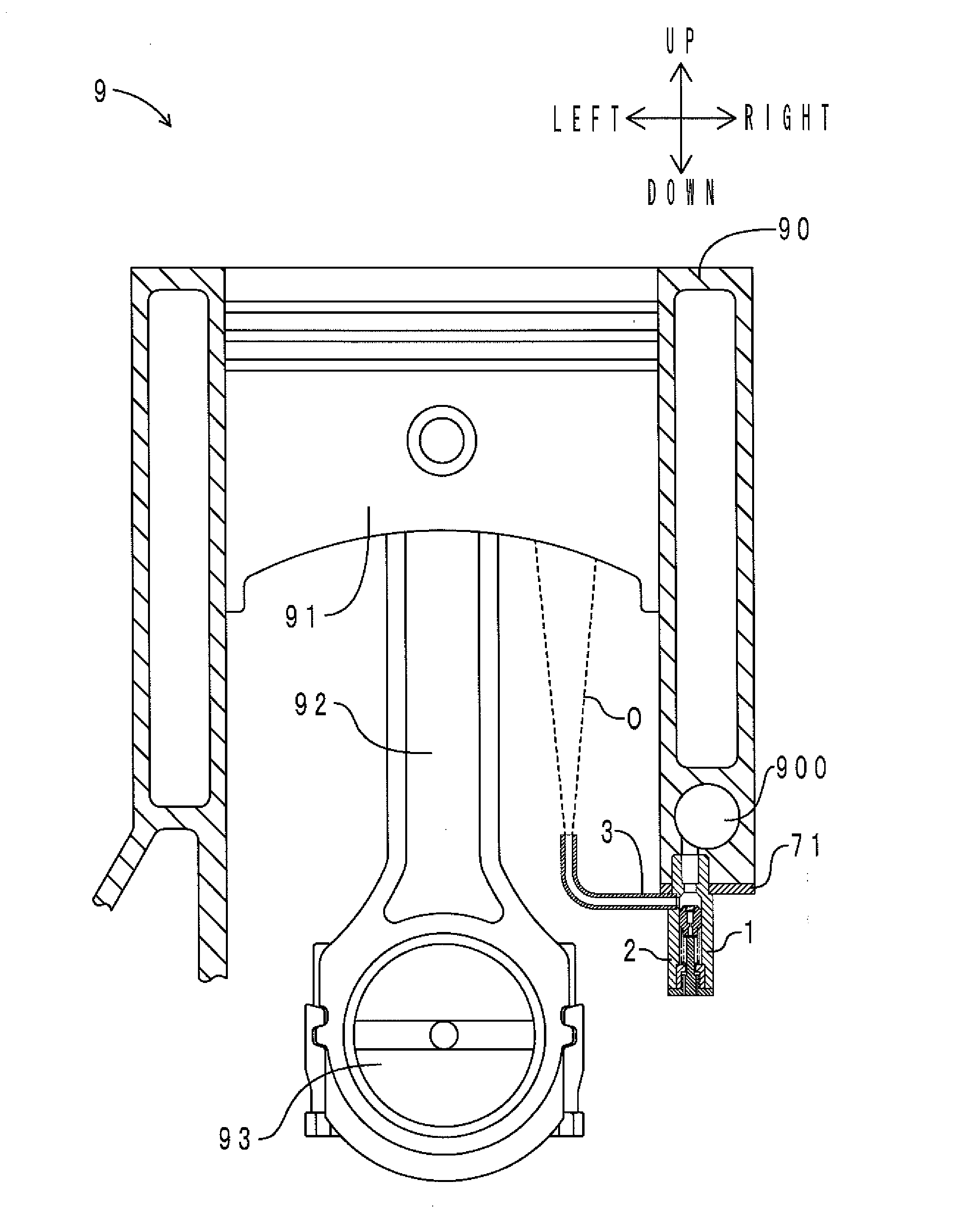
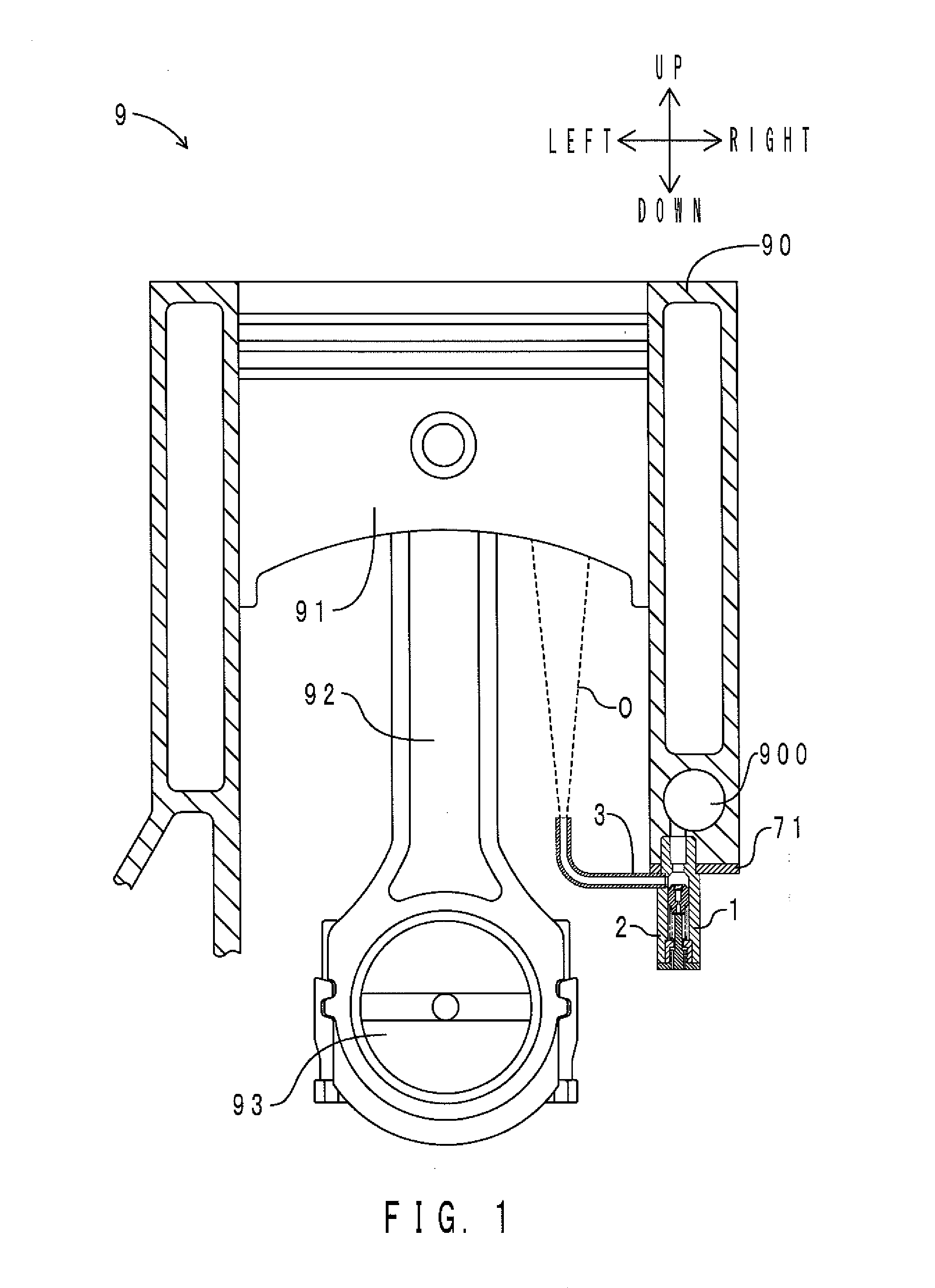
[0039]First, the arrangement of the piston cooling jet according to the embodiment will be described. FIG. 1 shows the arrangement of the piston cooling jet according to the embodiment. As shown in FIG. 1, an engine 9 includes a cylinder block 90, a piston 91, a connecting rod 92, and a crankshaft 93.

[0040]The piston 91 is connected to the crankshaft 93 via the connecting rod 92. The piston 91 is reciprocally movable in the up-down direction in the cylinder block 90. A main oil gallery 900 is formed in the cylinder block 90. The main oil gallery 900 is included in the concept of the “engine-side oil passage” according to the present invention. A piston cooling jet 1 is attached to the cylinder block 90.

[0041]Oil is circulated in the engine 9 through an oil pan (not shown), a pump (not shown), an oil filter (not shown), the cylinder block 90, the piston cooling jet 1, and again the oil pan. That is, in the oil circulation circuit, the cylinder block 9...

second embodiment

[0094]A piston cooling jet according to a second embodiment is different from the piston cooling jet according to the first embodiment in that the filter is disposed downstream of the orifice. Another difference is that a rib is disposed on the inner peripheral surface of the housing in the piston cooling jet according to the second embodiment. Only such differences will be described below.

[0095]FIG. 7 is an enlarged sectional view, in the up-down direction, of the piston cooling jet according to the embodiment in the valve closed state. Components corresponding to those of FIG. 6 are denoted by the same reference symbols. As shown in FIG. 7, the filter 75 covers an opening at the lower end of the valve-side oil passage 40. The filter 75 is disposed downstream of the orifice A. The lower surface of the valve 4 has a planar shape. The upper surface of the shaft 62 has a planar shape.

[0096]An annular rib 73 is disposed on the inner peripheral surface of the housing 2 (inner peripheral...


PUM


Abstract

A piston cooling jet includes a housing, a nozzle, a valve, a pressure chamber, a pressure adjusting passage, and a filter. The nozzle is provided to project outward from the housing, and capable of spraying oil toward a piston. The valve is capable of moving reciprocally inside the housing, and configured to receive a load due to a hydraulic pressure in an engine-side oil passage applied from a front side of the valve. The valve includes a valve-side oil passage that communicates with the engine-side oil passage. The pressure chamber communicates with the valve-side oil passage. The pressure adjusting passage is disposed between the pressure chamber and a space outside the housing. The filter is disposed in the valve, and configured to remove foreign matter that cannot pass through the pressure adjusting passage from oil passing through the valve-side oil passage.

Description

INCORPORATION BY REFERENCE[0001]The disclosure of Japanese Patent Application No. 2012-218928 filed on Sep. 29, 2012 including the specification, drawings and abstract is incorporated herein by reference in its entirety.BACKGROUND OF THE INVENTION[0002]1. Field of the Invention[0003]The present invention relates to a piston cooling jet that cools a piston of an engine by spraying oil toward the back surface of the piston.[0004]2. Description of Related Art[0005]A piston cooling jet is attached to a cylinder block of an engine. The piston cooling jet communicates with a main oil gallery of the cylinder block. The main oil gallery forms a part of an oil circulation circuit of the engine. The piston cooling jet is provided with a hydraulic valve mechanism.[0006]When the hydraulic pressure of oil in the main oil gallery is equal to or more than a predetermined threshold, the hydraulic valve mechanism of the piston cooling jet is opened. This causes oil in the main oil gallery to be spra...

Claims


Application Information

Patent Timeline
Patent Type & Authority Applications(United States)
IPC IPC(8): F01P3/08
CPCF01P3/08F01M1/08
Inventor YAMAGUCHI, YOSHITAKAKAWAHARA, MASAHIROMURAKAMI, MOTOICHIHONDA, AKIHIRO
Owner TAIHO INDUSTRIES CO LTD
Why Eureka
Try Eureka