Control rod for nuclear reactor and method of manufacturing control rod

a control rod and nuclear reactor technology, applied in nuclear engineering, nuclear elements, greenhouse gas reduction, etc., can solve the problems of reducing the life of the flux trap-type hafnium control rod, threatening the safety of the nuclear reactor, and revealing no technique for reducing residual stresses

Inactive Publication Date: 2014-04-10
KK TOSHIBA
View PDF6 Cites 2 Cited by
  • Summary
  • Abstract
  • Description
  • Claims
  • Application Information

AI Technical Summary

Benefits of technology

[0024]The present invention is effective in preventing stress corrosion cracking, effective in reducing electrochemical activation, effective in reducing blade history, effective in improving axial mechanical strength distribution, and effective in enhancing manufacturability.
[0037]The manufacturing method may further include a step of placing fixing members for fixing in a thickness direction of each wing of the neutron absorber at positions located in a vicinity of bases of the wings and arranged in a longitudinal direction to prevent distortion of a rectangular tube having a cross shape in horizontal cross section.
[0038]The manufacturing method may further include a step of placing fixing members for fixing in a direction of a base of each wing at positions arranged in a longitudinal direction and located at the bases of the wings which are opposed to each other to prevent distortion of a rectangular tube having a cross shape in horizontal cross section.
[0048]The control rod may further include a hafnium-zircaloy composite material and short narrow hafnium rods, wherein the hafnium-zircaloy composite material is repeatedly mount-folded and valley-folded so as to provide mount-folded and valley-folded portions which are arranged at equal intervals and which extend in parallel to each other, the valley-folded folded portions are brought close to each other so that the folded hafnium-zircaloy composite material has a cross shape in horizontal cross section, and the hafnium rods are arranged in end portions of the wings in form of spacers. The control rod may further include a tie cross made of zircaloy, wherein the valley-folded portions partially have longitudinal holes regularly and intermittently arranged in the axial direction and portions of the tie cross are arranged above and below the longitudinal holes so as to maintain the cross shape and improve mechanical strength.
[0049]The control rod may further include short narrow hafnium rods functioning as spacers, wherein the four hafnium-zircaloy composite members are bent so as to provide an L-shape, bent portions of the hafnium-zircaloy composite members are brought close to each other so as to be directed to a center of a cross shape, and the hafnium rods are attached to end portions of the bent hafnium-zircaloy composite members. The control rod may further include a tie cross made of zircaloy, wherein the bent portions partially have longitudinal holes regularly and intermittently arranged in the axial direction and portions of the tie cross are arranged above and below the longitudinal holes so as to maintain the cross shape and improve mechanical strength.
[0055]According to the present invention of the characters mentioned above, the control rod is effective in suppressing stress corrosion cracking and / or electrochemical activation. When the control rod is used in a nuclear reactor, the inconveniences, encountered in the prior art, caused by a difference in irradiation growth or a difference in thermal expansion can be solved and the reduction in reactivity worth is suppressed, which can solve a problem that a fuel assembly adjacent to the control rod generate a large amount of power when the control rod is removed from the nuclear reactor (i.e. a problem of serious blade history). The neutron-absorbing plates can be processed so as to have a uniform thickness in the axial direction, thereby improving manufacturability, reducing manufacturing cost, and enhancing mechanical health.

Problems solved by technology

This leads to a reduction in the life of the flux trap-type hafnium control rod 200 and may threaten the safety of nuclear reactor.
However, Patent Document 1 discloses no technique for reducing residual stresses caused by welding.
This leads to a reduction in the reliability of the flux trap-type hafnium control rod 200.
No techniques for preventing stress corrosion cracking are disclosed in conventional technical documents.
However, there are problems in that an increase in the number of the hafnium plates 205 leads to an increase in manufacturing cost and the hafnium plates 205 are nonuniform in mechanical strength in the axial direction (that is, the hafnium plates 205 located at lower positions have lower mechanical strength).
Furthermore, the control rod 200 suffers from corrosion because the atmosphere in the nuclear reactor is corrosive.
However, no measure against corrosion or no measure against a problem, called blade history, are disclosed in Patent Document 3.
Therefore, portions of fuel assemblies that are adjacent to neutron absorbers have a low neutron flux level and therefore burn slowly.
The prevention of a reduction in neutron flux is effective in solving this problem and usually reduces the reactivity worth of the long-life control rod, thereby causing a shortage in reactivity worth.
However, it has become clear that the conventional control rods are susceptible to stress corrosion cracking and are electrochemically activated.
In order to use the conventional control rods in nuclear reactors for a long time, problems caused by a difference in irradiation growth or a difference in thermal expansion need to be solved and the following problem also needs to be solved in such a manner that a reduction in reactivity worth is suppressed, i.e., a problem that fuel assemblies adjacent to the conventional control rods generate a large amount of power when the conventional control rods are removed from the nuclear reactors (that is, a problem that blade history is serious).

Method used


Image

  • Control rod for nuclear reactor and method of manufacturing control rod
  • Control rod for nuclear reactor and method of manufacturing control rod
  • Control rod for nuclear reactor and method of manufacturing control rod

Examples


first embodiment

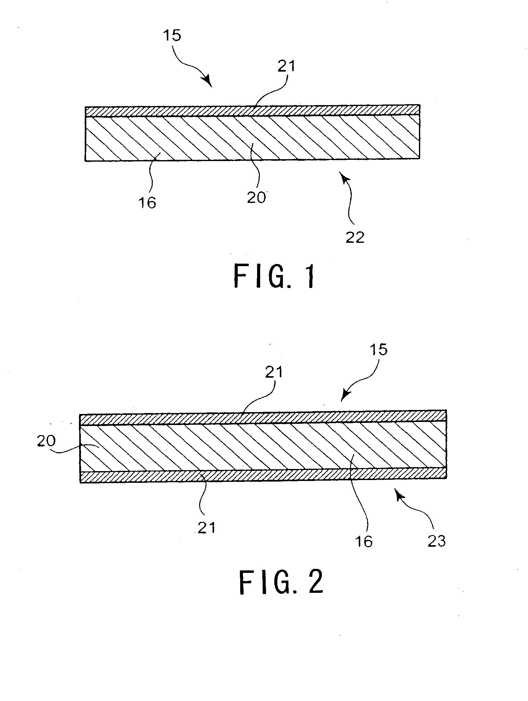
[0093]FIG. 1 is a partial sectional view of a neutron absorber 16 included in a control rod 15 according to a first embodiment of the present invention. The control rod 15 itself has a general structure such as shown in FIG. 30. The neutron absorber 16 includes a hafnium plate 20 bonded to a zirconium plate 21 by means of hot rolling or the like. The hafnium plate 20 and the zirconium plate 21 form a composite member 22.

[0094]A conventional control rod, of the structure mentioned with reference to FIGS. 30 to 32, for example, includes U-shaped sheaths having fitting portions, hafnium plates, and supporting pieces having projecting portions bonded to the fitting portions by TIG welding. If the conventional control rod is exposed to high-temperature water in a nuclear reactor in such a state that the U-shaped sheaths have high residual tensile stress due to welding, stress corrosion cracking occurs in the U-shaped sheaths to deteriorate the performance of the conventional control rod....

second embodiment

[0097]FIG. 2 is a partial sectional view of a neutron absorber 16 included in a control rod 15 according to a second embodiment of the present invention. In this embodiment, the neutron absorber 16 includes a composite member 23 including a hafnium plate 20 and zirconium plates 21 bonded to both surfaces of the hafnium plate 20 by means of hot rolling or the like as shown in FIG. 2.

[0098]The hafnium plate 20 is protected from high-temperature, high-pressure water that is a moderator, and hence, the corrosion of the neutron absorber 16 can be prevented and the creation of oxides in the control rod 15 can be suppressed. This allows the control rod 15 to have a long life.

third embodiment

[0099]A third embodiment of the present invention provides a method of manufacturing the control rod 15 according to the first embodiment. The control rod 15 includes the composite member 22, which includes the hafnium plate 20 and the zirconium plate 21.

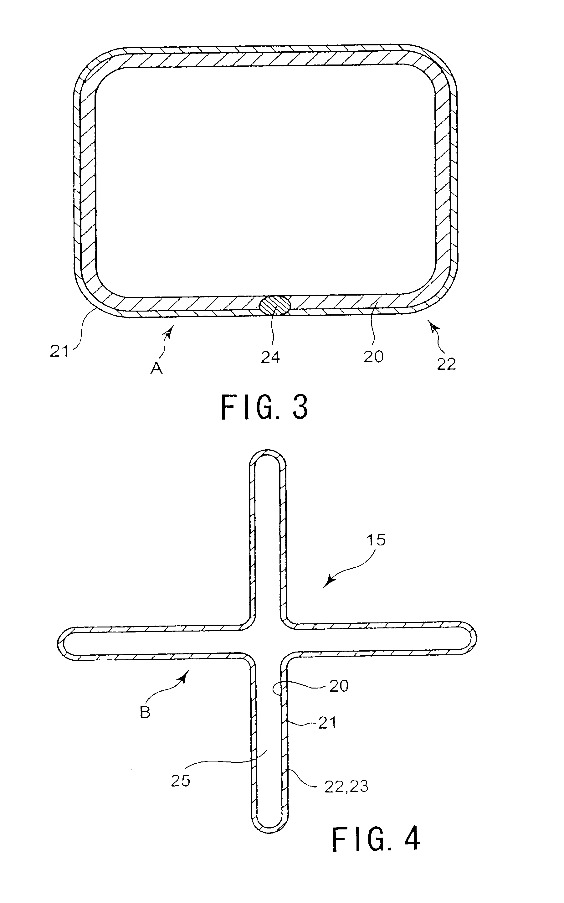
[0100]As shown in FIG. 3, after the composite member 22, which has been prepared by bonding the hafnium plate 20 and the zirconium plate 21 together by means of rolling, for example, is shaped so as to have such a box shape that the zirconium plate 21 is located outside the hafnium plate 20, end portions of the composite member 22 are bonded to each other with a welding member 24 or the like, whereby a rectangular tube A is prepared.

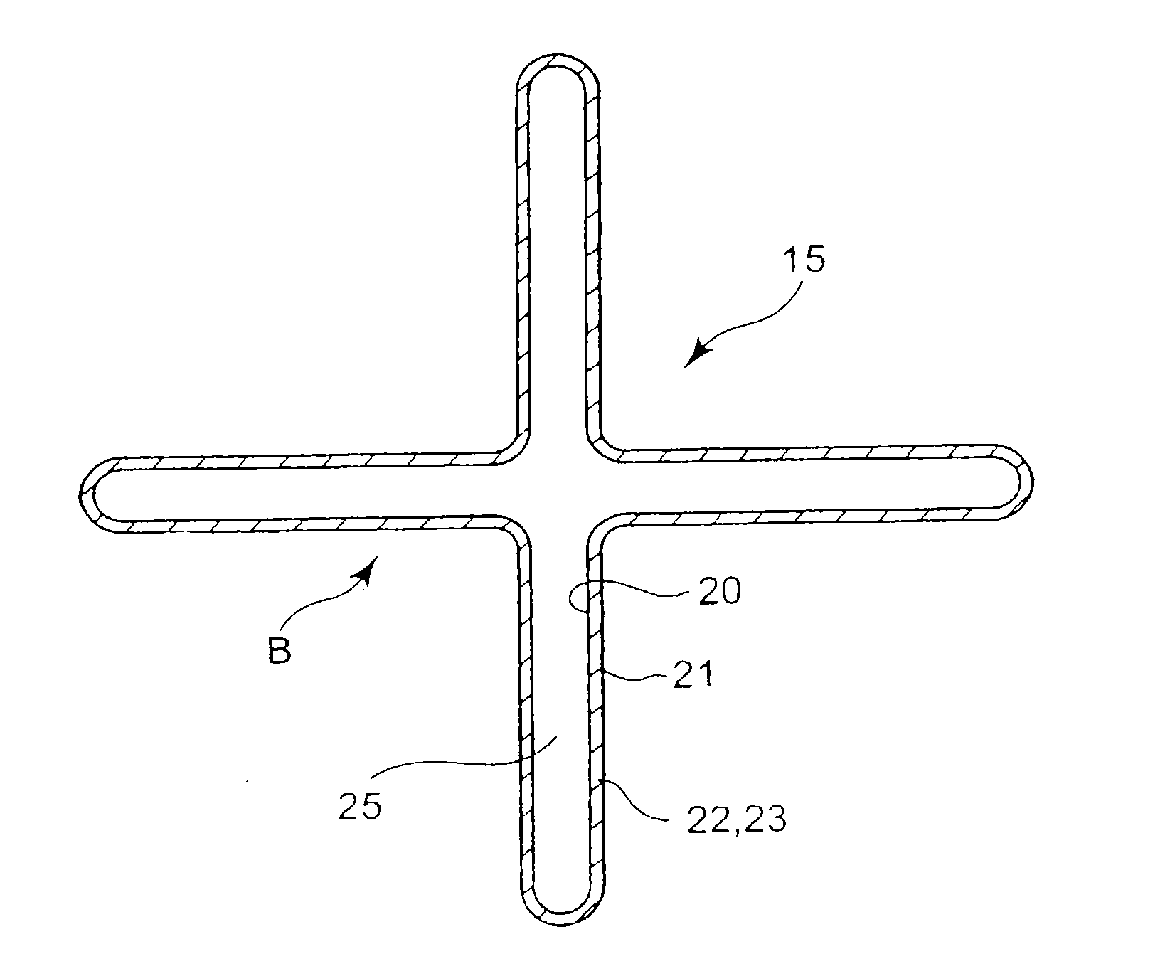
[0101]As shown in FIG. 4, the rectangular tube A is molded into a cross-shaped tube B such that the zirconium plate 21 is located outside the hafnium plate 20. The cross-shaped tube B has an inner space 25 which has a cross shape in cross section and through which water used as a moderator can flow. As s...


PUM


Abstract

A control rod for nuclear reactors includes four wings including neutron absorbers containing hafnium, a front end structural member which has a cross shape in cross section and includes brackets bonded to the leading ends of the wings, and a terminal end structural member which has a cross shape in cross section and includes brackets bonded to the tailing ends of the wings. The four wings are bonded to a wing-bonding member including a cross-shaped center shaft so as to form a cross shape. The front end structural member and the wing-bonding member are made of a zirconium alloy. The wings include neutron-absorbing plates having neutron-absorbing portions and each have an outer surface which is opposed to a fuel assembly and at which a hafnium-zircaloy composite member covered with zircaloy is disposed. The neutron-absorbing plates are opposed to each other with trap spaces disposed therebetween.

Description

CROSS-REFERENCE TO RELATED APPLICATIONS[0001]This application is a continuation of and claims the benefit under 35 U.S.C. §120 from U.S. application Ser. No. 12 / 034,966, filed Feb. 21, 2008, which claims priority under 35 U.S.C. §119 from Japanese Patent Application No. 2007-042444, filed Feb. 22, 2007 and Japanese Patent Application No. 2007-321907, filed Dec. 13, 2007, the entire contents of each of which are hereby incorporated.BACKGROUND OF THE INVENTION[0002]1. Field of the Invention[0003]The present invention relates to a control rod for nuclear reactors such as boiling water reactors and also relates to a method for manufacturing such a control rod.[0004]2. Related Art[0005]One example of a conventional control rod having a long life for boiling water reactor (BWR) is shown in FIGS. 30 to 32 with reference numeral of 200 as disclosed in Japanese Unexamined Patent Application Publication No. 63-8594 (hereinafter referred to as Patent Document 1) or a publication by M. Ueda, T....

Claims


Application Information

Patent Timeline
Patent Type & Authority Applications(United States)
IPC IPC(8): G21C7/113
CPCG21C7/113G21C21/18Y02E30/30
Inventor SAITO, YUUJINAKAMURA, MITSUHARUUEDA, MAKOTOKATAYAMA, YOSHINORITSUBOTA, MOTOJITAJIMA, SATOKOKARINO, YOSHIJIYOSHIOKA, KENICHITSUMITA, KOSAKU
Owner KK TOSHIBA
Why Eureka
Try Eureka