
Method to mitigate propagation loss in waveguide transmission of quantum states

a waveguide transmission and waveguide technology, applied in the field of quantum communication, can solve the problems of reducing the quality of unknown states, reducing the throughput of transmission loss exponentially, and losing photons in optical fibers, and achieve the effect of facilitating quantum communications

Active Publication Date: 2014-04-10
PERSPECTA LABS INC
View PDF1 Cites 44 Cited by
  • Summary
  • Abstract
  • Description
  • Claims
  • Application Information

AI Technical Summary

Benefits of technology

The patent describes a method for enhancing quantum communications by generating and separating photons in an unknown quantum state. The photons are then transmitted through one or more channels that balance transmission loss and gain. These channels may contain analysis interferometers and single-photon detectors to measure the photons. The technical effect is an improved efficiency and accuracy in quantum communications.

Problems solved by technology

One problem typically encountered during transmission is that photons are lost in the optical fiber.
As a result, a major challenge in quantum communications (QC) is that transmission loss exponentially reduces the throughput.
When a signal comprising photons in unknown quantum states is amplified, enough noise is added such that the quality of the unknown state is degraded typically to the point of making it unusable for quantum communications protocols.
This amplification of unknown quantum states, often called quantum cloning, necessarily causes a reduction in state quality.
As a result, many quantum communications applications, such as Quantum Key Distribution (QKD), have generally been considered to be either impossible or impractical when quantum states are transmitted through amplifiers.
If a third party attempts to “steal” a photon, copy it, send on the copy to another location, errors in transmission of the photons are necessarily introduced.
As a result, the presence of such errors indicate that the transmitted photons are no longer suitable for information use in some quantum communication protocols, such as quantum key distribution (QKD), and can trigger the protocol to be aborted.
Unfortunately, direct transmission of entangled photons is greatly limited by the transmission loss described above.
While the throughput drop due to attenuation appears to be a fundamental limitation, there is an additional limitation due to receiver noise, which also limits tolerable losses such that the received signal probability is greater than the detector noise probability, which ultimately limits practical applications to fiber spans less than 250 km (see for example, D. Stucki, N. Walenta, F. Vannel, R. T. Thew, N. Gisin, H. Zbinden, S. Gray, C. R. Towery and S. Ten, High Rate, “Long-Distance Quantum Key Distribution over 250 km of Ultra Low Loss Fibers,” New J. Phys. vol 11: 075003 (2009) and Y. Liu, T-Y Chen, J. Wang, W-Q Cai, X. Wan, L-K Chen, J-H Wang, S-B Liu, H. Liang, L. Yang, C-Z Peng, K. Chen, Z-B Chen, and J-W Pan, “Decoy-State Quantum Key Distribution With Polarized Photons over 200 km,” Optics Express vol.
While developed for Quantum Key Distribution applications, trusted relays do not work for general communication of quantum states (such as for example, the transmission of entangled states) because classical measurement at each relay destroys the quantum state and, for example, for a qubit, yields only a single classical bit.
Unfortunately, such quantum repeaters are not yet practical, although they are presently a focus of multiple research efforts.
However, even if they become successful, quantum repeaters would still be subject to latency problems from the classical communication required as part of the protocol.
In addition, as discussed above, current techniques for transmitting single-photon level signals though optical fibers in unknown quantum states are subject to exponential loss in throughput.
That waiting period, because of the non-deterministic transmission of the fiber, is a further cause of latency.
For example, if photons are transmitted at a gigabit per second, over a typical 200 km long fiber with total loss of 40 dB, even if all other components were ideal, only about one out of every 10,000 sent would be received, making direct transmission highly inefficient.

Method used


Image

  • Method to mitigate propagation loss in waveguide transmission of quantum states
  • Method to mitigate propagation loss in waveguide transmission of quantum states
  • Method to mitigate propagation loss in waveguide transmission of quantum states

Examples


Embodiment Construction

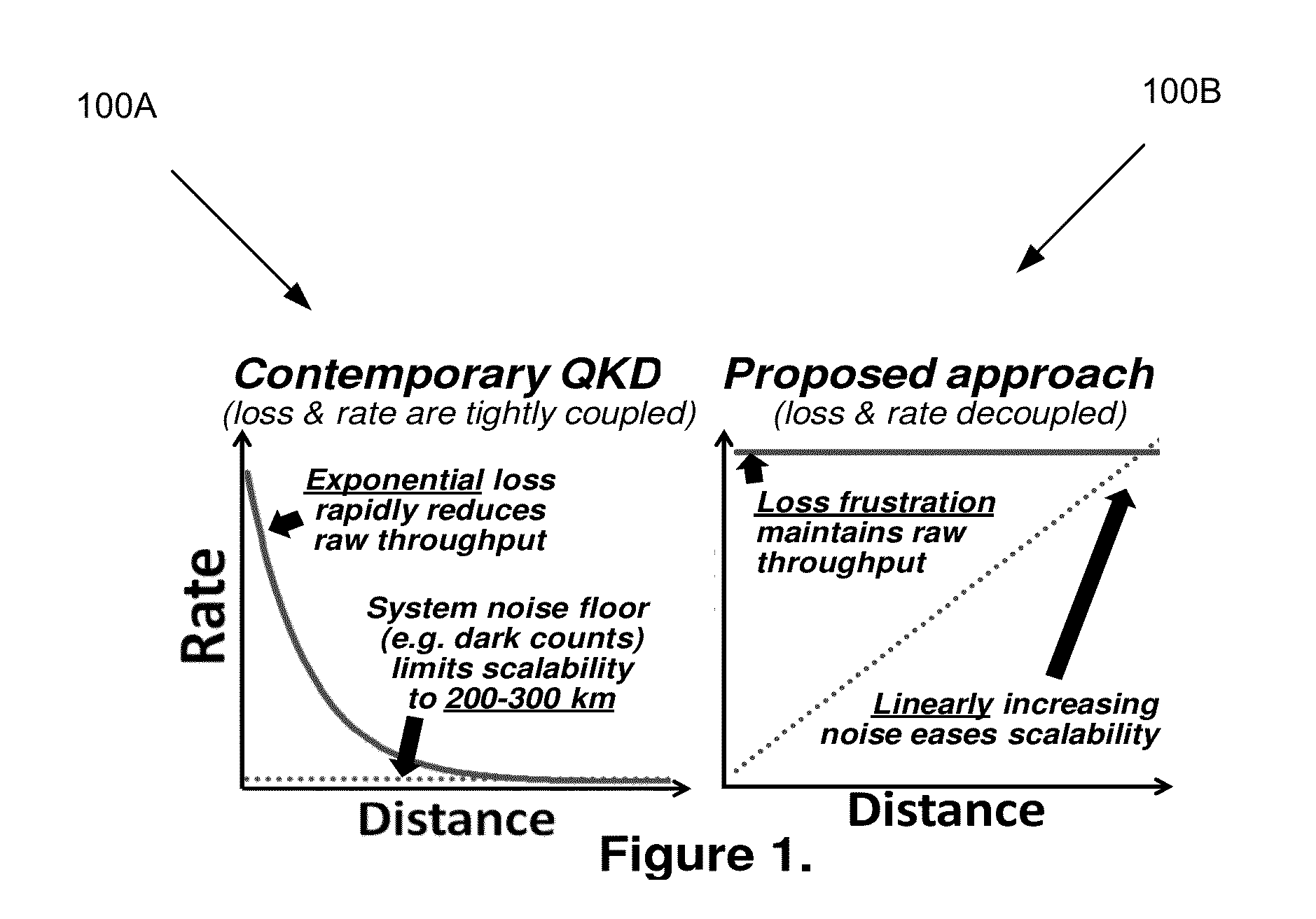
[0031]FIG. 1 shows a comparison of a graph 100A of relative performance of related art quantum communications transmission of photons in an optical medium compared to a graph 100B of same for examples of the present disclosure. Graph 100A shows that the transmission rate with distance into a medium for contemporary quantum state transmission falls off exponentially, rapidly reducing raw throughput. The rate falls off to a relatively constant low value of a noise floor. Loss and transmission rate are tightly coupled. In graph 100B, in contrast, transmission rate remains relatively high with distance into a medium, while noise increases only linearly with distance. Loss in the medium and transmission rate is decoupled.

[0032]Embodiments of the present disclosure decouple an expected exponential drop of quantum communications throughput with distance using a distributed optical phase sensitive amplifier (OPSA) for loss frustration tailored to a known entangled state. Because the entangl...


PUM


Abstract

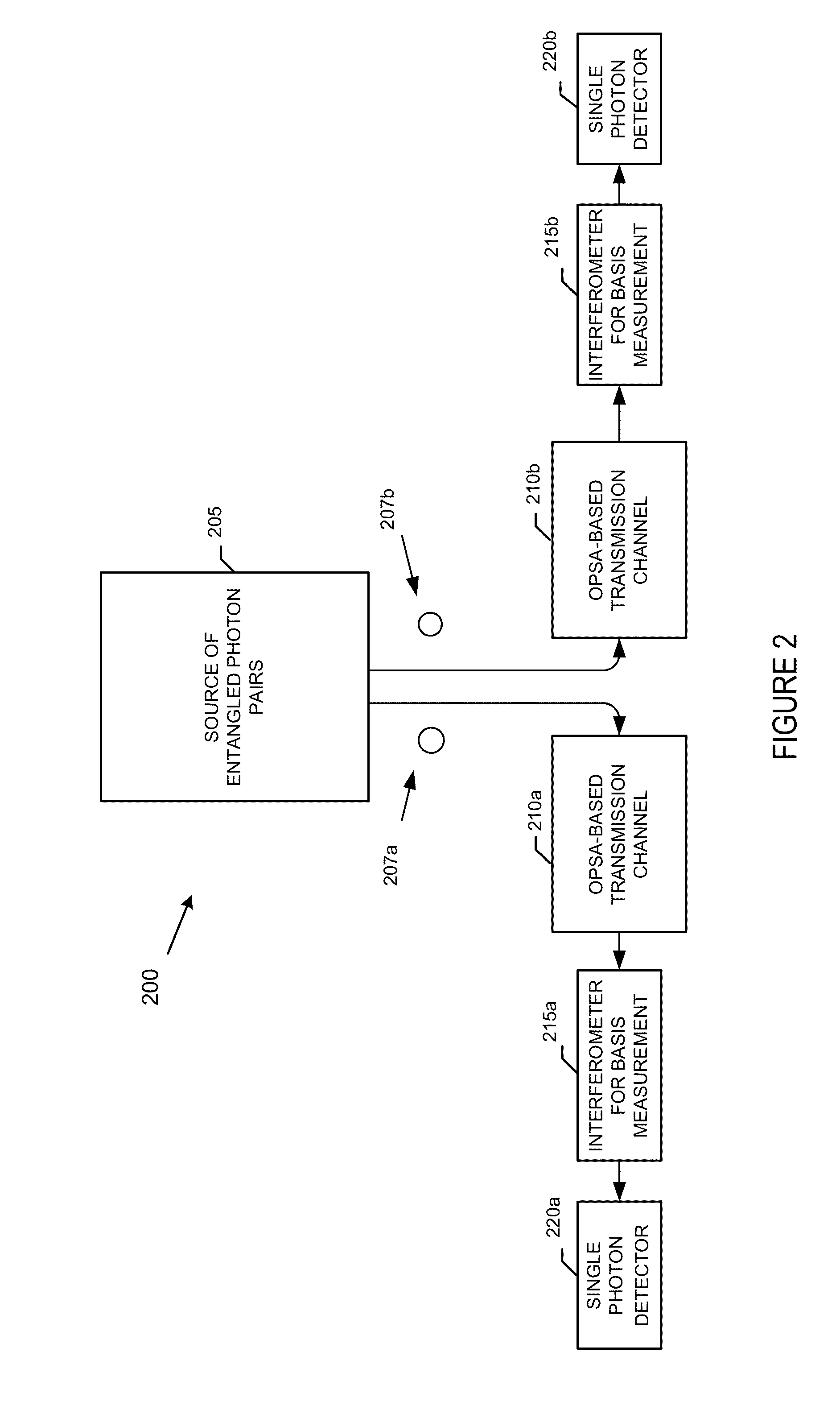
A system comprises a source of entangled photon pairs. The source is to place a signal photon and an idler photon in individual unknown quantum states but in a known entangled quantum state. One or more transmission channels are connected to the source. Each of the one or more transmission channels transmits one of the signal photon or the idler photon. Each of the one or more transmission channels is to substantially balance an instantaneous transmission loss with an instantaneous transmission gain distributed over a transmission distance. Analysis interferometers are configured to receive a corresponding one of the signal photon or the idler photon. Each of the one or more analysis interferometers is to perform a basis measurement on one of the signal photon or the idler photon. Single-photon detectors detect one of the signal photon or the idler photon.

Description

CROSS-REFERENCE TO RELATED APPLICATIONS[0001]This application claims the benefit of U.S. provisional patent application No. 61 / 709,698 filed Oct. 4, 2012, the disclosure of which is incorporated herein by reference in its entirety.FIELD OF THE INVENTION[0002]The present invention relates to quantum communications. More particularly, the present invention relates to a system and method for facilitating quantum communications.BACKGROUND OF THE INVENTION[0003]Quantum communications typically involves transmission of photons in unknown quantum states. Information may be encoded and transmitted in an optical fiber as a transmission channel in either a single-photon state or a two-photon state. One problem typically encountered during transmission is that photons are lost in the optical fiber. Even if a nearly perfect transmitter is employed that emits a perfect single-photon state or a two-photon state each time, the number of photons that make it through the optical fiber transmission c...

Claims


Application Information

Patent Timeline
Patent Type & Authority Applications(United States)
IPC IPC(8): H04B10/2507
CPCH04B10/2507H04B10/70H04L9/0852
Inventor PETERS, NICHOLAS A.AGARWAL, ANJALITOLIVER, PAUL
Owner PERSPECTA LABS INC
Learn More