Thermal energy battery with enhanced heat exchange capability and modularity

a technology of thermal energy storage and heat exchange capacity, applied in the direction of cell components, lighting and heating apparatus, domestic cooling apparatus, etc., can solve the problems of reducing the heat exchange capacity of the battery, unable to be easily separated and used for other refrigeration applications, and not being able to maintain a constant discharge rate, etc., to achieve the effect of increasing heat exchange capacity

Active Publication Date: 2014-04-17
PROMETHEAN POWER SYST
View PDF15 Cites 65 Cited by
  • Summary
  • Abstract
  • Description
  • Claims
  • Application Information

AI Technical Summary

Benefits of technology

[0015]This invention overcomes the disadvantages of the prior art by combining the compactness and modularity of encapsulated phase-change materials with the benefits and simplicity of gravity as a motive force to increase heat exchange capability and provide a more constant rate of discharge.

Problems solved by technology

Electrical power consumption peaks during the day and dips significantly at night.
By way of example, in many rural areas of India grid electricity is only available for a limited time during the day or night.
In this disclosure, the ice-based energy storage system is built into and is an integral part of the milk cooling tank, therefore cannot be easily separated and used for other refrigeration applications.
Disadvantageously, no provision is made for maintaining a constant discharge rate, other than having sufficient surface area for heat transfer.
This is a common and well known method described in prior art, but it makes the battery less compact than it can otherwise be.
Furthermore, by relying only on surface area for heat transfer, the battery will not be able to maintain a constant output during discharge because the heat exchange surface area becomes smaller as the PCM begins to melt.
However, the system is not modular, is difficult to build and cannot be easily sized for other applications.
However this is a very expensive method of forming ice on copper tube coils.
These devices suffer from the same limitation as they can not maintain a constant output and discharge rate for long periods of time.
This system does not use phase-change materials and thus cannot be very compact.
Furthermore, the system described in this disclosure is limited to heat storage and cannot be easily adapted to refrigeration and air conditioning applications.
A modular approach suited to refrigeration applications is described in US Patent 2002 / 0007637, but this method is expensive and relies on fixed path-ways that can only be changed manually using expensive quick-disconnects.

Method used


Image

  • Thermal energy battery with enhanced heat exchange capability and modularity
  • Thermal energy battery with enhanced heat exchange capability and modularity
  • Thermal energy battery with enhanced heat exchange capability and modularity

Examples


Embodiment Construction

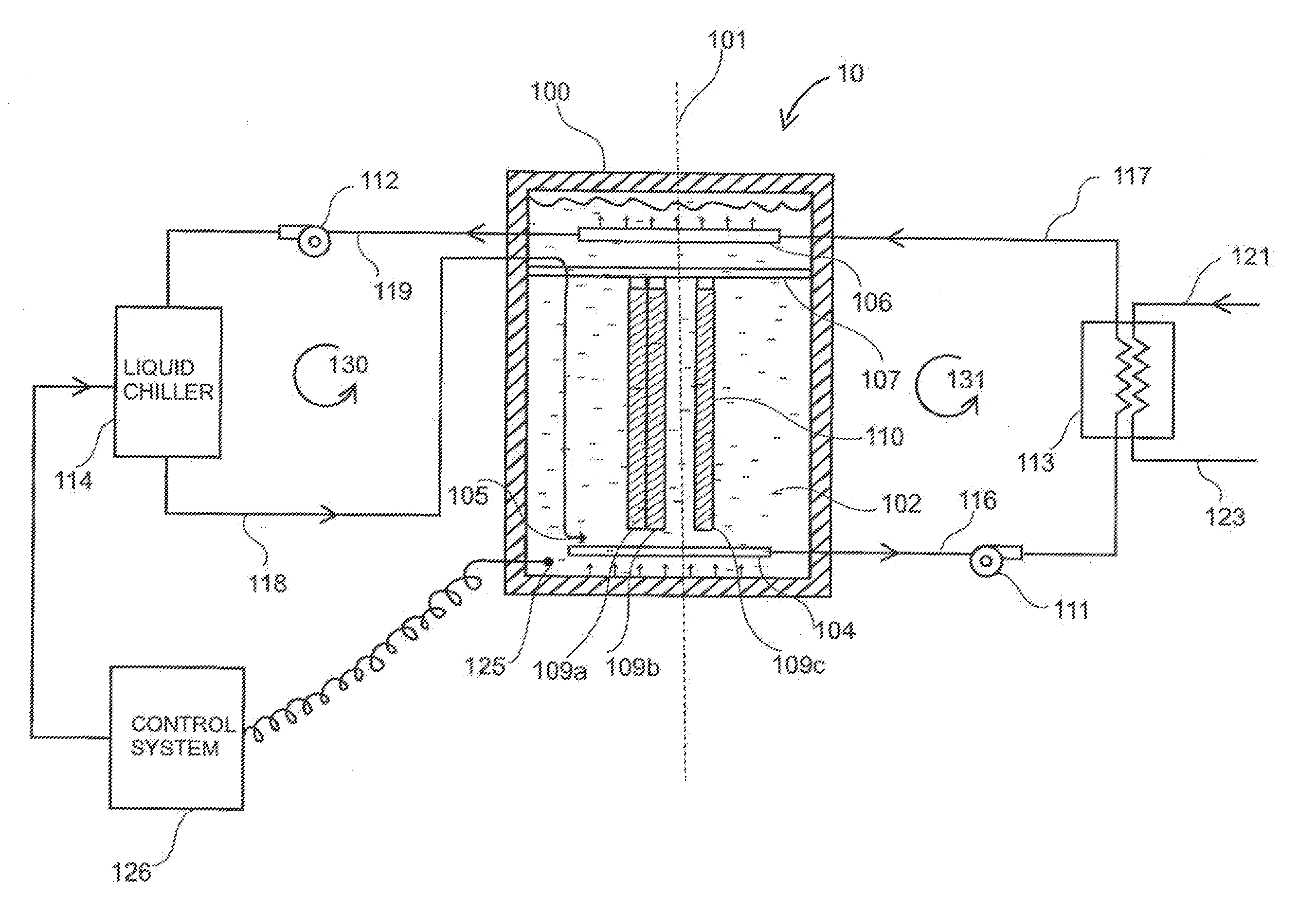
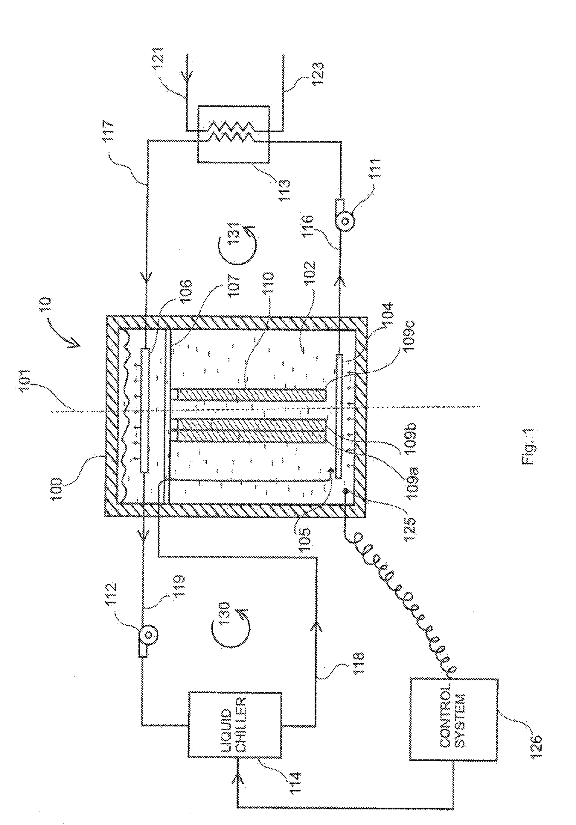
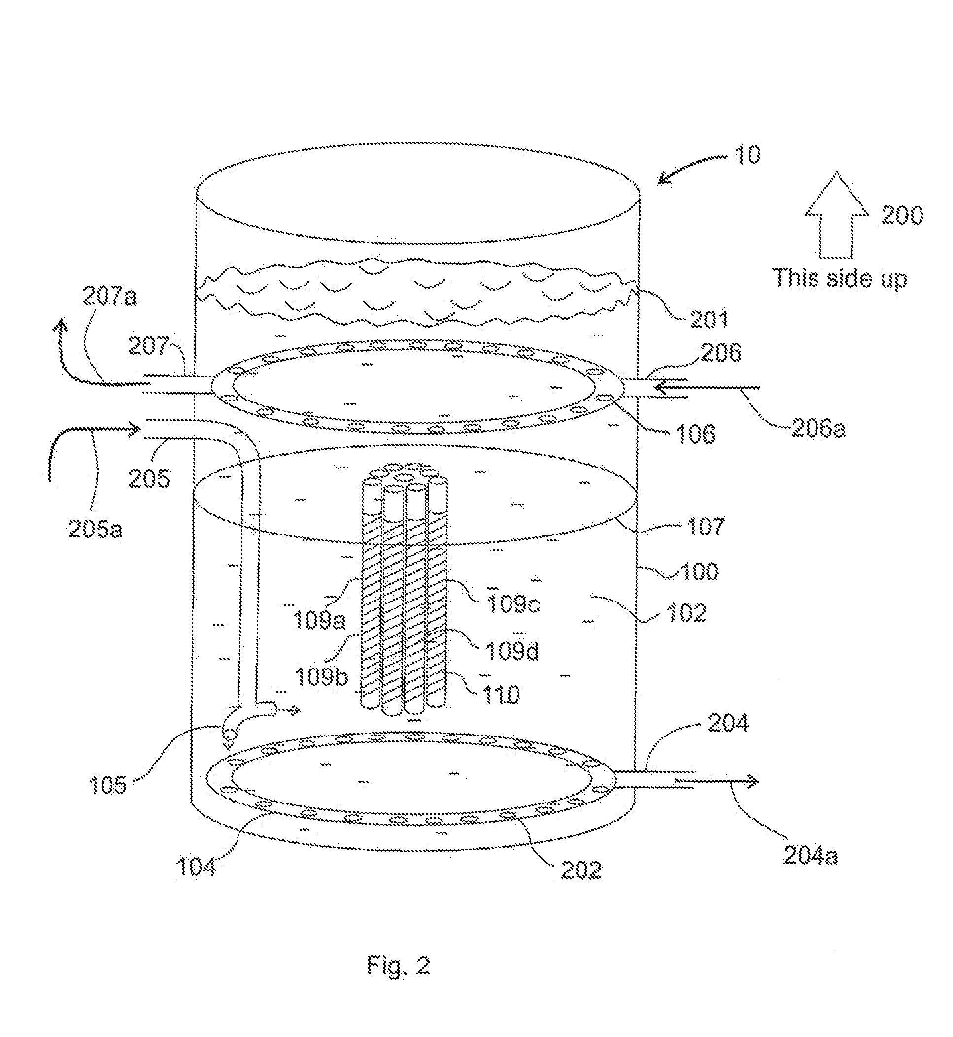
[0031]According to an illustrative embodiment, a compact and modular thermal energy storage (TES) battery is shown and described herein. Also shown and described are systems and methods for charging and discharging the illustrative battery and systems and methods for connecting multiple batteries to form a thermal energy storage bank.

[0032]A thermal energy battery 10 and all associated components to charge and discharge the battery are shown in FIG. 1. The TES battery 10 comprises of an insulated container 100 oriented vertically about axis 101. Container 100 is filled with heat transfer fluid (HTF) 102. In an illustrative embodiment, HTF 102 is a mixture of water and 30% isopropyl alcohol, the freezing point of which is −15 degrees C. (5 degrees F.). The mixture is based on a predetermined freezing point. Other HTF mixtures can also be used, such as water and propylene glycol (PPG), in proper proportion to ensure a depressed freezing point below the freezing point of the chosen pha...


PUM

PropertyMeasurementUnit
latent heat of fusionaaaaaaaaaa
volumeaaaaaaaaaa
volumeaaaaaaaaaa

Abstract

This invention provides a thermal energy battery having an insulated tank contains a multitude of densely packed plastic tubes filled with a phase-change material (PCM, such as ice) that changes from solid to liquid and vice-versa. Energy is stored when the PCM transitions from liquid to solid form, and released when the PCM transitions back from solid to liquid form. The tubes are arranged vertically, span the height of a well-insulated tank, and are immersed in heat transfer fluid (HTF) contained within the tank. The HTF is an aqueous solution with a freezing point temperature below the freezing point temperature of the chosen PCM. The HTF remains in liquid form at all times during the operation of the battery. Diffusers located allow the HTF to be extracted uniformly from the tank, pumped and cooled by a liquid chiller situated outside the tank and then and inserted back into the tank.

Description

RELATED APPLICATION[0001]This application claims the benefit of U.S. Provisional Application Ser. No. 61 / 711,833, filed Oct. 10, 2012, and entitled THERMAL ENERGY BATTERY WITH ENHANCED HEAT EXCHANGE CAPABILITY AND MODULARITY, by Sorin Grama, et al, the teachings of which are expressly incorporated herein by reference.FEDERALLY SPONSORED RESEARCH OR DEVELOPMENT[0002]This invention was made with United States Government support under Grant #1113206 awarded by the National Science Foundation. The U.S. Government has certain rights in this invention.FIELD OF INVENTION[0003]The present invention relates to thermal energy storage systems, and more particularly to a phase-change energy storage system for refrigeration and air conditioning applications.BACKGROUND OF THE INVENTION[0004]During a 24-hour period, the electrical grid experiences a large variation in demand. Electrical power consumption peaks during the day and dips significantly at night. Energy storage is often employed to miti...

Claims


Application Information

Patent Timeline
Patent Type & Authority Applications(United States)
IPC IPC(8): F28D20/00
CPCF28D20/00A01J9/04C09K5/063F25B2400/24F25D16/00F25D31/002F25D31/006F28D20/0034F28D20/02F28D20/021F28D20/023F28D20/028F28D2020/0069Y02E60/14Y10T29/49108
Inventor GRAMA, SORINDORSON, MATTHEW H.CHRISTIANSON, REBECCA
Owner PROMETHEAN POWER SYST
Why Eureka
Try Eureka