Energy storage system

a technology of energy storage and energy storage, applied in the field of energy storage systems, can solve the problems of limiting the system life, deteriorating battery health, and limited warranty on batteries in conventional hybrid systems, and achieves the effects of increasing efficiency, no loss of efficiency, and achieving greater efficiency

Inactive Publication Date: 2014-04-17
RICARDO UK LTD
View PDF2 Cites 30 Cited by
  • Summary
  • Abstract
  • Description
  • Claims
  • Application Information

AI Technical Summary

Benefits of technology

[0029]By providing an auxiliary electrical machine, coupled to the flywheel, it is possible to use stored battery power to pre-charge (spin-up) the flywheel at startup, and re-charge the flywheel after an acceleration event. It is also possible to use flywheel energy to run auxiliary electrical devices (for example, in place of a conventional car alternator), return stored flywheel energy to the battery for long-term storage (rather than simply losing the stored flywheel energy after switch-off due to friction) so as to increase efficiency, and also to limit flywheel charging during regeneration in cases where the flywheel is already fully charged (exce

Problems solved by technology

Problems exist with known hybrid systems since the high cycling frequency of the hybrid battery system charge level caused by, for example, regenerative braking and recovery during a typical vehicle usage scenario and the high power flows associated with these operations accelerate the deterioration of battery health, thereby limiting the system life.
Warranty is thus often limited on batteries in conventional hybrid systems.
Furthermore, battery cycling may be limited by protective control systems which control distribution of power supply and/or charging in a hybrid system.
An effect of this protective limiting is to impair the CO2 reduction efficacy of the corresponding hybrid system.
However, a problem with existing flywheel implementations remains that of how to charge the flywheel initially and at points of low energy therein.
Another problem with existing flywheel implementations is that when, for example, a vehicle is brought to rest and the engine (e.g. an Internal Combustion Engine or ICE) is switched off, the flywheel remains rotating and charged with kinetic energy.
This kinetic energy is gradually lost as the fl

Method used


Image

  • Energy storage system
  • Energy storage system
  • Energy storage system

Examples


Embodiment Construction

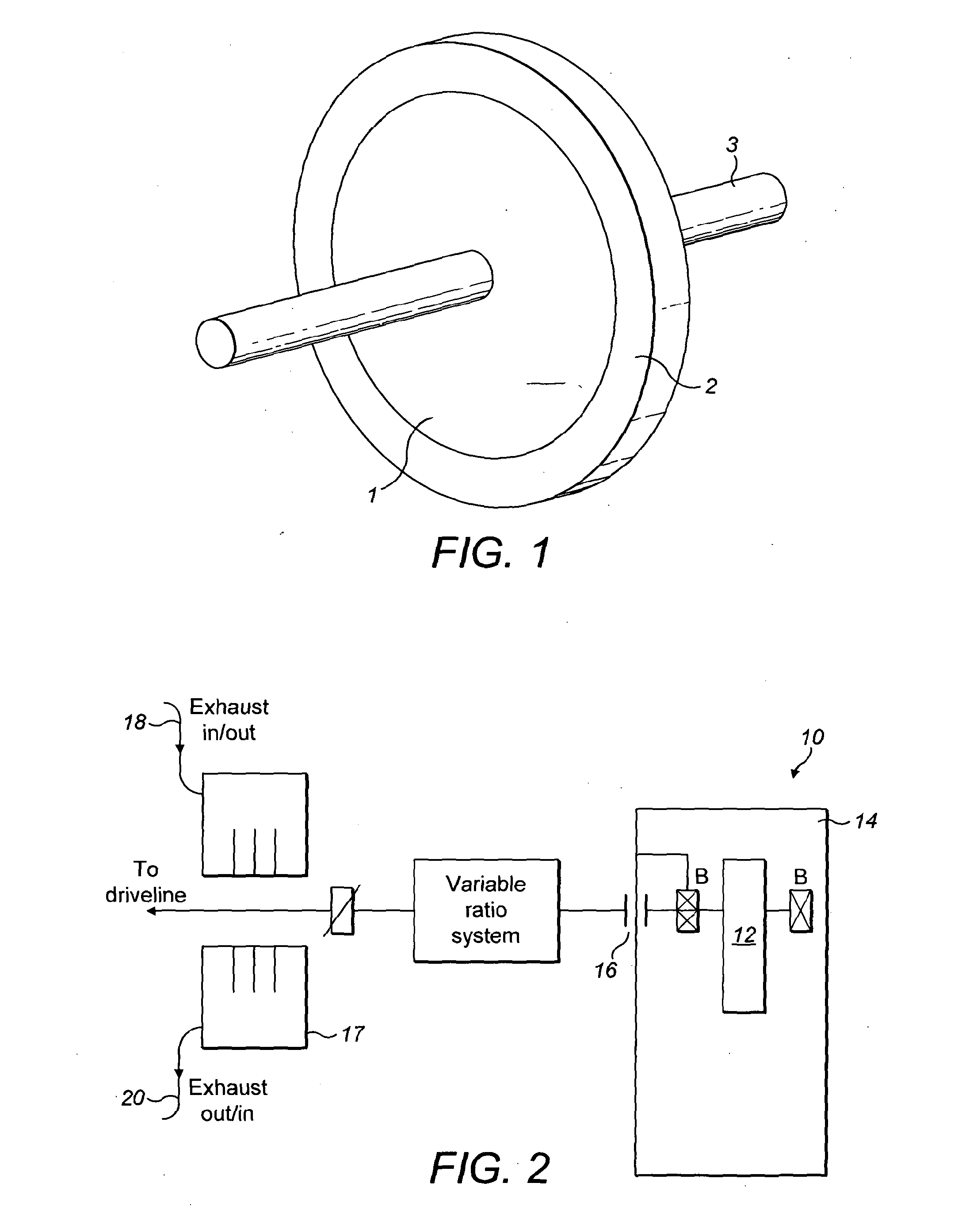
[0088]FIG. 1 shows a typical existing flywheel arrangement. A substantially circular central metallic support section 1 can be axially mounted on a central support such as a shaft 3. At least one composite ring 2 is mounted on the central support section 1. In the flywheel shown in FIG. 1, the composite ring 2 is filament wound from carbon fibre. As will be known to the skilled person, and as discussed above, a flywheel device such as the one shown in FIG. 1 can be used as a mechanical battery to store kinetic energy for use, for example, within a motor vehicle.

[0089]Examples of related technologies which can be applied to such a vehicle will first be described, followed by a description of an embodiment.

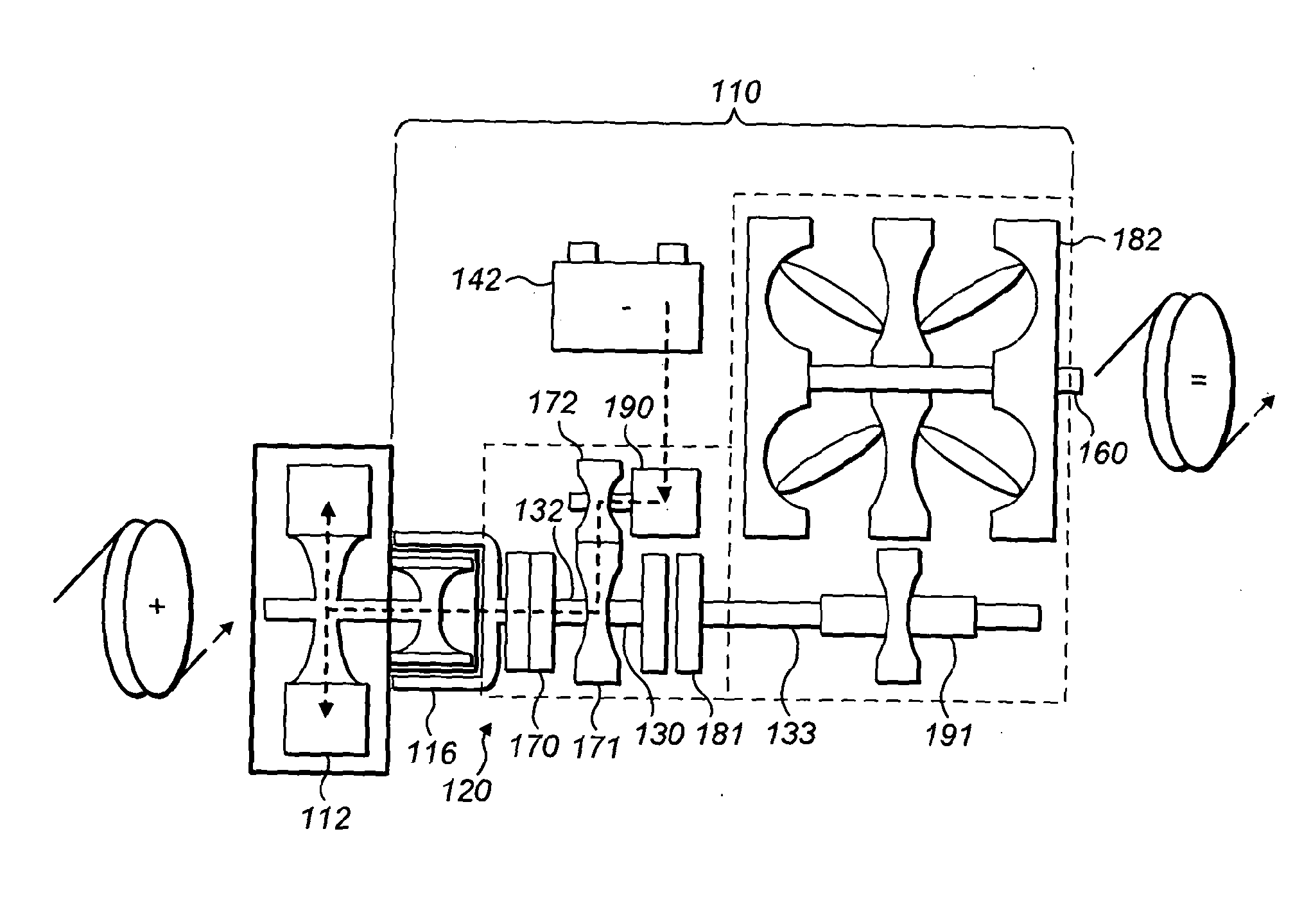
[0090]Exhaust—Driven Flywheel

[0091]Another example approach for optimising energy supply and its conversion from the stored chemical energy to torque, particularly in ICE powered motor vehicles is the use of turbochargers and superchargers. As will be known to the skilled person, tu...


PUM


Abstract

An apparatus is provided comprising a flywheel (112) for storing kinetic energy and an electrical machine (190) mechanically coupled to the flywheel and arranged for conversion between mechanical and electrical energy. The apparatus is arranged for transferring energy between the flywheel and a vehicle transmission via a variable ratio transmission (182). The electrical machine is coupled to the flywheel via a disconnect clutch which comprises a magnetic coupling (116).

Description

[0001]This invention relates to a flywheel energy storage apparatus and a method of controlling energy flow.BACKGROUND OF THE INVENTION[0002]The conservation and optimal use of energy is a key consideration in the manufacture and running of modern vehicles and machinery. There is an increasing user demand for efficiency and for obtaining the best possible output at the lowest possible cost to the user. Considerations in this cost / output balance include both financial and environmental factors. In addition, there is a demand for improved power and speed from vehicles and machinery, whilst at the same time a desire to provide a comfortable and user friendly feel. Furthermore, there is a trend for engines, motors and other equipment to become ever more compact and streamlined.[0003]There are many known approaches for dealing with the above discussed balance. For example, as user demand for environmentally friendly vehicles grows and the regulations on carbon emissions become ever stric...

Claims


Application Information

Patent Timeline
IPC IPC(8): B60K6/30H02K51/00H02K7/02B60L50/30
CPCB60K6/30H02K51/00H02K7/025B60K6/105B60K2006/262B60L50/30B60Y2400/423B60Y2400/608H02K7/006H02K7/11H02K7/1815H02K49/104Y02E60/16Y02T10/62Y02T10/64Y02T10/70
Inventor ATKINS, ANDREW FARQUHARSHEPHERD, SIMONDAVIS, JONATHAN
Owner RICARDO UK LTD
Why Eureka
Try Eureka