Permanent magnet rotor and methods thereof

a permanent magnet rotor and magnet rotor technology, applied in the direction of magnetic circuits, magnetic circuits characterised by magnetic materials, magnetic circuit shapes/forms/construction, etc., can solve the problems of limited life of adhesives and dramatic increase in the cost of rare earth magnets, so as to increase reduce the loss of electric motor efficiency. , the effect of increasing the efficiency of electric motors

Active Publication Date: 2014-04-17
REGAL BELOIT AMERICA
View PDF21 Cites 17 Cited by
  • Summary
  • Abstract
  • Description
  • Claims
  • Application Information

AI Technical Summary

Benefits of technology

[0005]In one embodiment, an electric machine is provided. The electric machine includes a machine housing and a stator disposed at least partially within the housing, the stator including a plurality of teeth and an aluminum winding wound around at least one tooth of the plurality of teeth. The electric machine further includes a radially embedded permanent magnet rotor disposed at least partially within the housing, the rotor including at least one radially embedded permanent magnet and configured to provide increased flux to reduce motor efficiency loss compared to a copper winding.
[0008]In yet another embodiment, a method of manufacturing an electric machine is provided. The method includes providing a machine housing and disposing a stator at least partially within the housing. The stator includes a plurality of teeth and an aluminum winding wound around at least one tooth of the plurality of teeth. The method further includes disposing a radially embedded permanent magnet rotor at least partially within the housing. The rotor includes at least one radially embedded permanent magnet and is configured to provide increased flux to reduce motor efficiency loss compared to a copper winding.
[0010]In yet another embodiment, a method of manufacturing an electric machine is provided. The method includes providing a machine housing and disposing a stator at least partially within the housing. The stator includes a plurality of teeth and a winding wound around at least one tooth of the plurality of teeth. The method further includes disposing a rotor at least partially within the housing, the rotor including at least one permanent magnet and configured to rotate with respect to the stator. The rotor includes a length shorter than a length of the stator such that the rotor reduces at least one of flux output, flux density and core loss of the electric machine during operation of the electric machine at a speed higher than the typical design speed of the electric machine.
[0011]In yet another embodiment, a method of increasing efficiency of an electric motor having aluminum windings without adjusting the length of the motor is provided. The method includes providing a motor housing and providing a stator at least partially in the motor housing. The stator includes a plurality of teeth and the aluminum windings are wound around at least one tooth of the plurality of teeth. The method further includes providing a rotor at least partially in the motor housing, the rotor including at least one permanent magnet, and increasing the flux output of the motor to reduce efficiency loss of the electric motor compared to copper windings.
[0012]In yet another embodiment, a method of increasing efficiency of an electric motor operating at speeds higher than the design speed of the motor is provided. The method includes providing a motor housing and providing a stator at least partially in the motor housing, the stator including a winding wound around at least one tooth. The method further includes providing a rotor at least partially in the motor housing, the rotor including at least one permanent magnet, and reducing at least one of the flux density, flux output and core loss of the motor when operating the motor at the higher speeds. The method further includes operating the electric motor at speeds higher than the typical design speed.

Problems solved by technology

However, adhesives have a limited life due to factors such as temperature, temperature cycling, and environmental conditions.
However, the cost of rare earth magnets has drastically risen in recent years, prompting the need for low-cost permanent magnet systems that generate similar amounts of flux and provide efficiencies similar to systems using rare earth magnets.

Method used


Image

  • Permanent magnet rotor and methods thereof
  • Permanent magnet rotor and methods thereof
  • Permanent magnet rotor and methods thereof

Examples


Embodiment Construction

[0035]Due to increased costs of rare earth magnets and copper used for windings, lower cost alternative materials are desirable in the design and manufacture of electric motors. This disclosure provides designs and methods using material alternatives to rare earth magnets and copper windings while reducing or recapturing the efficiency losses associated with those alternative materials and reducing or eliminating an increase of the length of the motor.

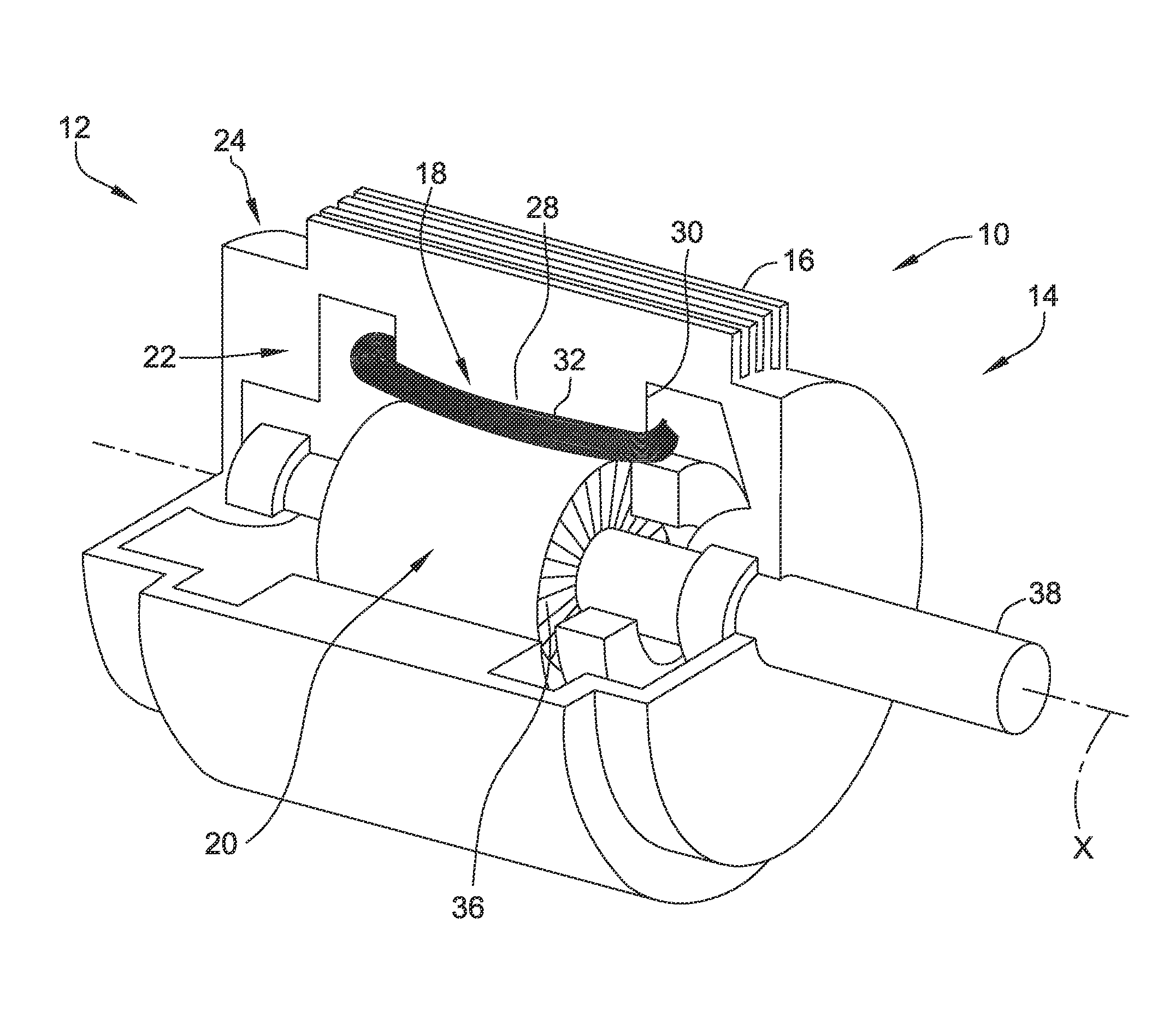
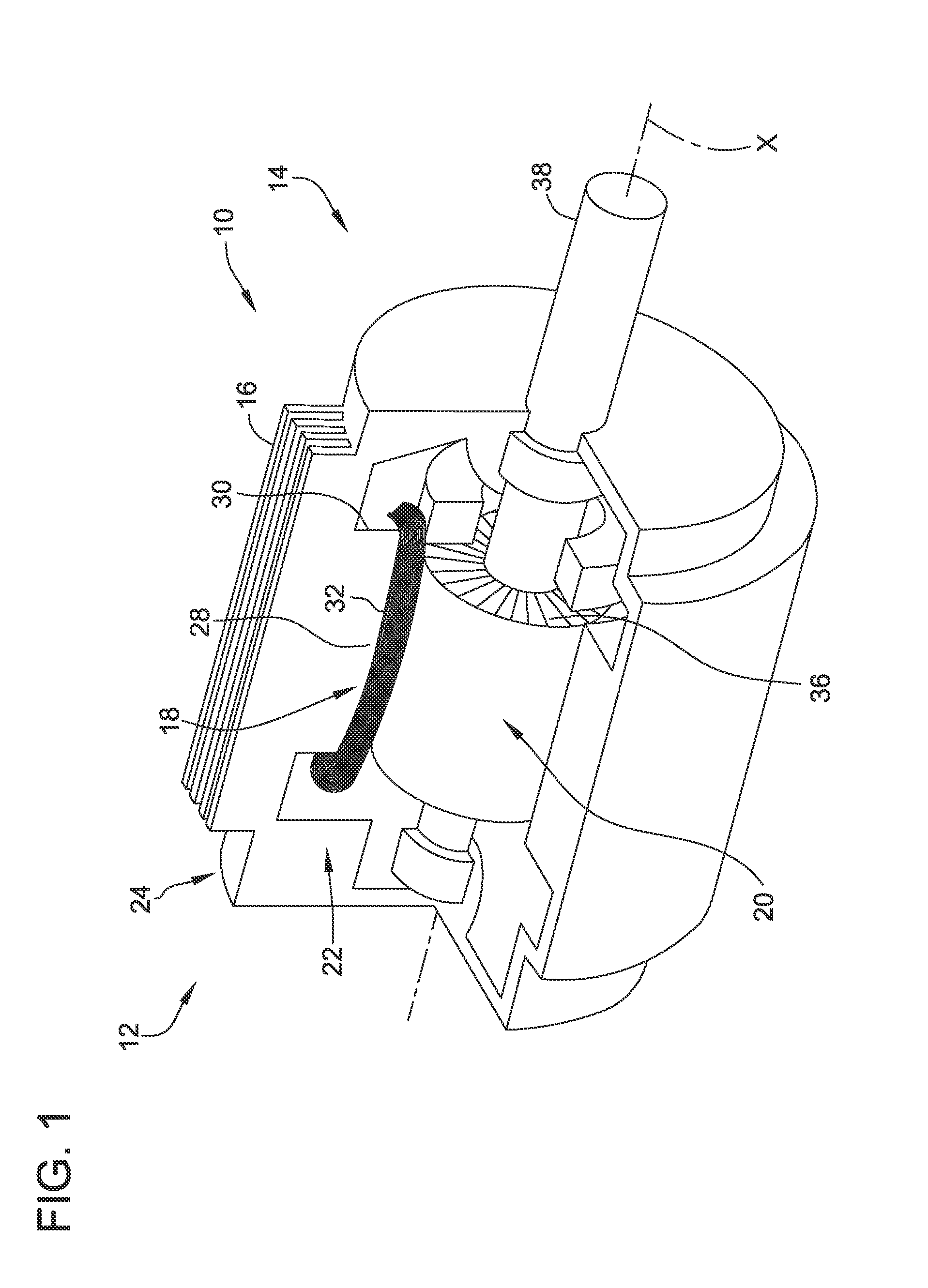
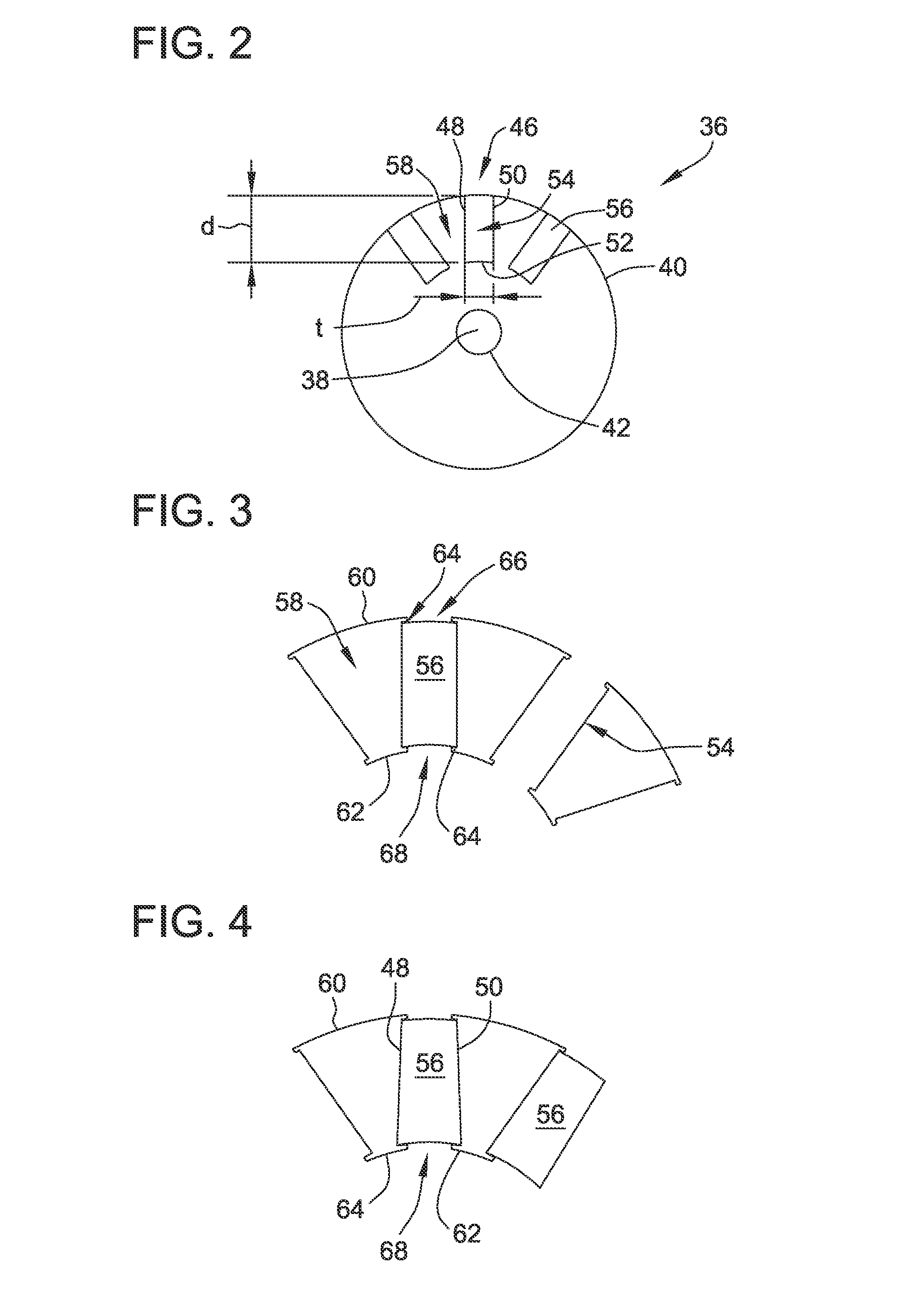
[0036]FIG. 1 is a perspective cut-away view of an exemplary electric motor 10. Although referred to herein as electric motor 10, electric motor 10 can be operated as either a generator or a motor. Electric motor 10 includes a first end 12, a second end 14, and a motor assembly housing 16. Electric motor 10 also includes a stationary assembly 18 and a rotatable assembly 20. Motor assembly housing 16 defines an interior 22 and an exterior 24 of motor 10 and is configured to at least partially enclose and protect stationary assembly 18 an...


PUM

PropertyMeasurementUnit
magnetic flux densityaaaaaaaaaa
lengthsaaaaaaaaaa
lengthaaaaaaaaaa

Abstract

In one embodiment, an electric machine is provided. The electric machine includes a machine housing and a stator disposed at least partially within the housing, the stator comprising a plurality of teeth and an aluminum winding wound around at least one tooth of the plurality of teeth. The electric machine further includes a radially embedded permanent magnet rotor disposed at least partially within the housing, the rotor comprising at least one radially embedded permanent magnet and configured to provide increased flux to reduce motor efficiency loss compared to a copper winding.

Description

BACKGROUND[0001]The field of the disclosure relates generally to electric motors, and more particularly, to radially embedded permanent magnet rotors and alternative materials for use in electric motors.[0002]Various types of electric machines include permanent magnets. For example, a brushless direct current (BLDC) motor may include a plurality of permanent magnets coupled to an exterior surface of a rotor core. Typically, the permanent magnets are coupled to the exterior surface of the rotor core using an adhesive and / or an outer retaining covering. This coupling between the permanent magnets and the rotor core must resist forces exerted on the permanent magnets during high speed rotation tending to separate the permanent magnets from the motor.[0003]Permanent magnets may also be positioned within a rotor core, commonly referred to as an interior permanent magnet rotor. Slots are formed within the rotor, and magnets are inserted into the slots. The magnet slots must be larger than...

Claims


Application Information

Patent Timeline
Patent Type & Authority Applications(United States)
IPC IPC(8): H02K1/27H02K15/00
CPCH02K1/27H02K15/00H02K21/16H02K1/02H02K3/02H02K15/02H02K2213/03Y02P80/30Y10T29/49009H02K1/16
Inventor BRAHMAVAR, SUBHASH MARUTIRAO
Owner REGAL BELOIT AMERICA
Why Eureka
Try Eureka