Robot, robot control apparatus, robot control method, and robot control program

a robot control and robot technology, applied in the field of robots, can solve problems such as inability to realize complex tasks such as rotation with contact maintained

Active Publication Date: 2014-04-17
PANASONIC INTELLECTUAL PROPERTY MANAGEMENT CO LTD
View PDF3 Cites 50 Cited by
  • Summary
  • Abstract
  • Description
  • Claims
  • Application Information

AI Technical Summary

Benefits of technology

[0017]According to the robot, the robot control apparatus, the robot control method, and the robot control program according to the aspect of the present disclosure, an additional assist force is corrected into the corrected additional assist force by a correction vector of the assist force as a vector in a vertical direction based on an external force detected upon generation of the resistance force. For this reason, in the power assist robot using impedance control, the assist force is corrected from an actual assist force into an accurate assist force suitable for the task involving the contact so that the horizontal component of the resistance force or a component parallel to a wall surface is a desired resistance force vector, or a friction force caused by the contact between the gripped object and the external environment does not exceed the maximum static friction force. In this manner, the task involving the contact can be easily realized.

Problems solved by technology

In Patent Literature 1, however, only the stable contact is realized, and there is a problem that more complicated tasks such as rotation with the contact being maintained are not realized.

Method used


Image

  • Robot, robot control apparatus, robot control method, and robot control program
  • Robot, robot control apparatus, robot control method, and robot control program
  • Robot, robot control apparatus, robot control method, and robot control program

Examples


first embodiment

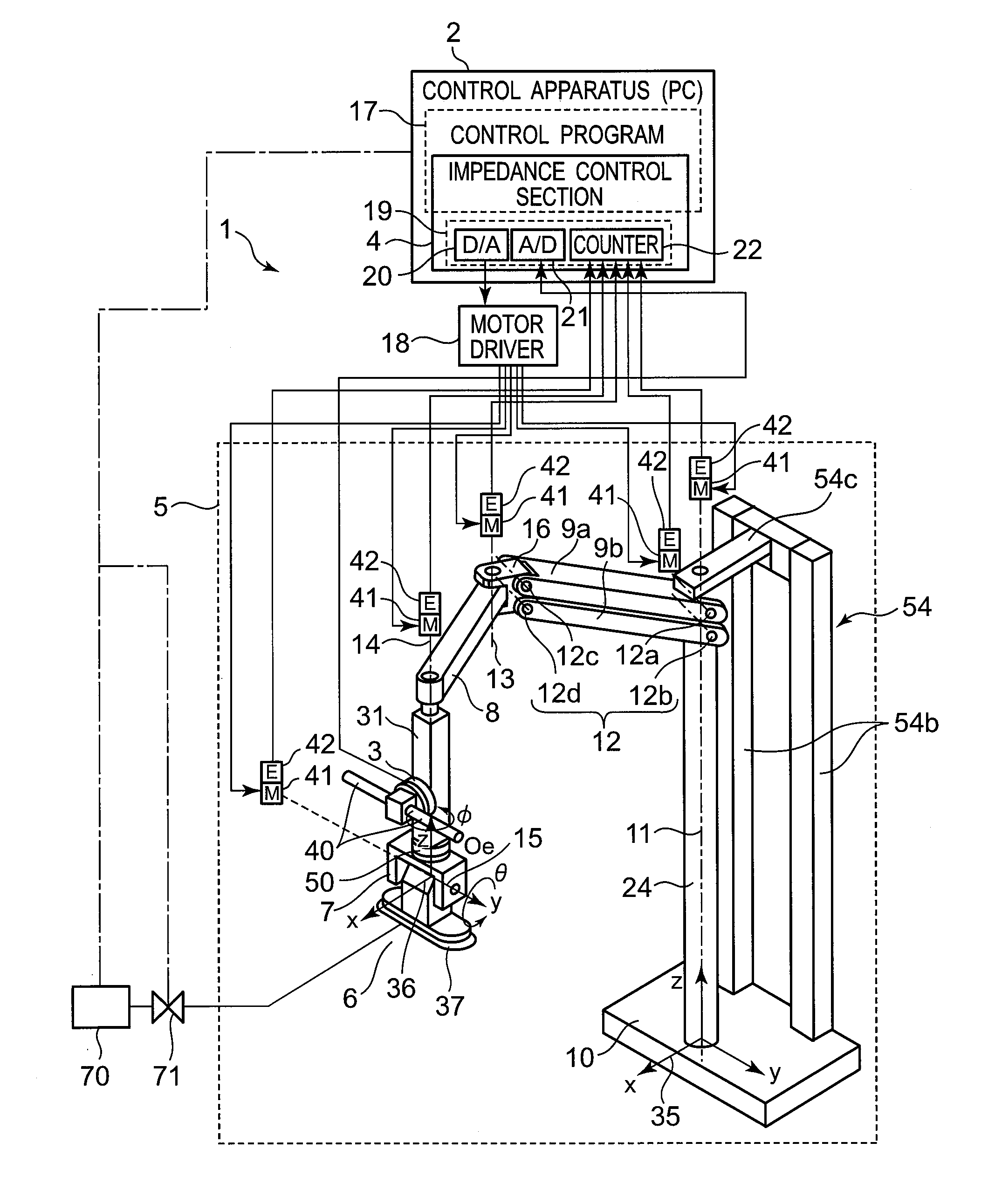
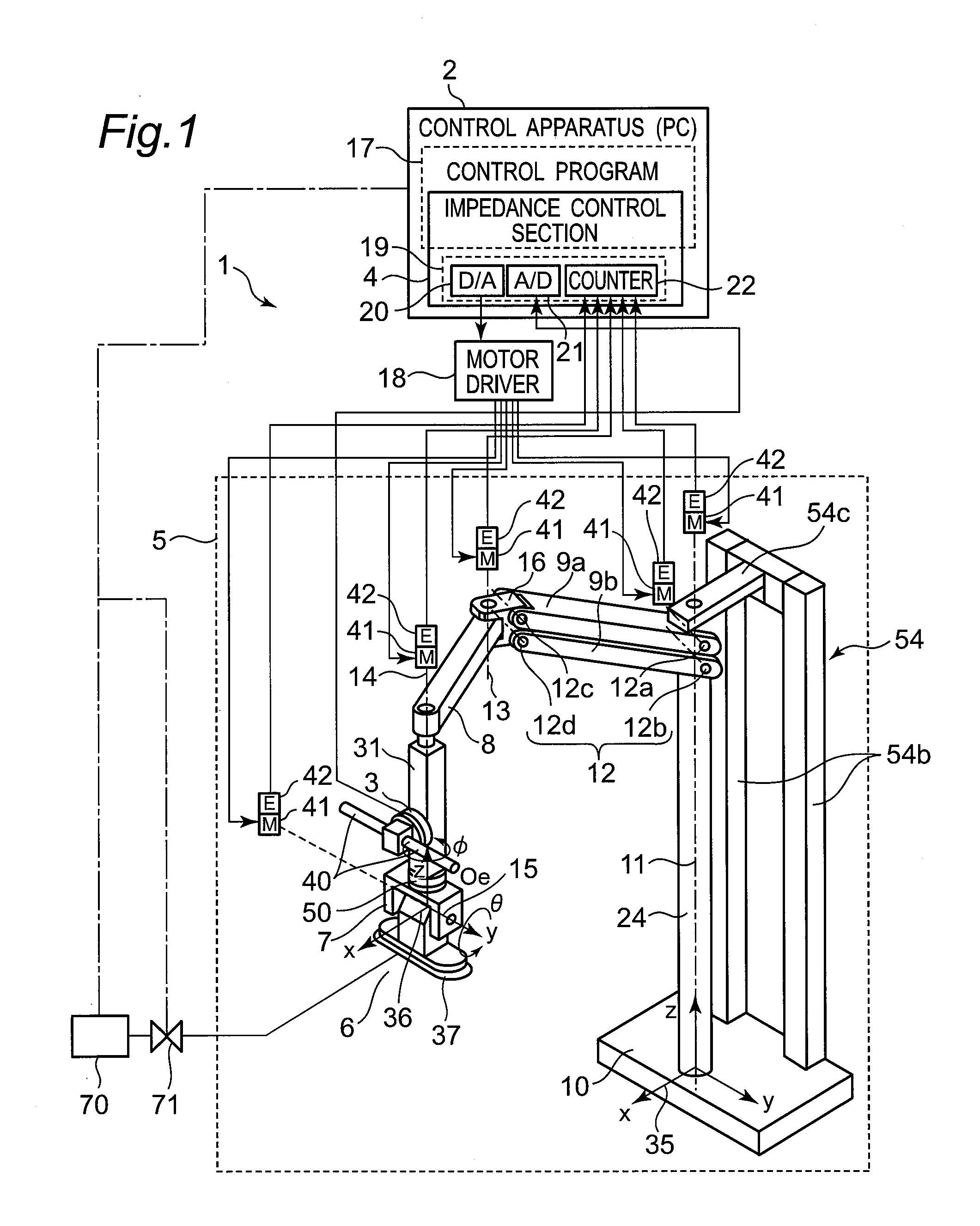
[0084]FIG. 1 illustrates a configuration of a robot 1 according to a first embodiment of the present disclosure. The robot 1 includes a multi-joint robot arm 5, and a control apparatus 2 for the robot 1 that controls a motion of the multi-joint robot arm 5.

[0085]The control apparatus 2 is configured by a general personal computer in hardware. Further, the control apparatus 2 except for an input / output IF 19 of the robot arm control section (robot arm controller) 4 is realized in software as a control program 17 executed by a personal computer. Therefore, for example, a computer program having steps constituting respective motions is stored readably in a recording medium such as a memory device (hard disc or the like), and the computer program is loaded into a temporary memory device (semiconductor memory or the like) of the computer so as to be run using a CPU and enable the respective steps to be executed.

[0086]The input / output IF 19 includes a D / A board 20, an A / D board 21, and a ...

second embodiment

[0171]Since the basic configuration of the robot 1 according to a second embodiment of the present disclosure is similar to that in the first embodiment shown in FIGS. 1 and 2A, the common portions are denoted by the same reference numerals as those in the first embodiment, and descriptions thereof are omitted. Only different portions are described in detail below.

[0172]The conveyance task according to the second embodiment will be described with reference to FIG. 9. In the second embodiment, an object 38 is not lifted by a robot arm 5 into a state of being separated from a floor surface 90, but an additional assist force 45 is applied from the robot arm 5 in a direction of lifting the object 38 with the object 38 touching the floor surface 90. As a result, a normal force 56 is reduced. In this manner, a motion of conveying the object 38 by the robot arm 5 can be conducted so as to drag the object 38 along the floor surface 90 with the object 38 in contact with the floor surface 90 ...

third embodiment

[0178]Since the basic configuration of the robot 1 according to a third embodiment of the present disclosure is similar to that in the first embodiment shown in FIGS. 1 and 2A, the common portions are denoted by the same reference numerals as those in the first embodiment, and description thereof are omitted. Only different portions are described in detail below.

[0179]A conveyance task of an object 38 according to the third embodiment will be described with reference to FIG. 10A to FIG. 10C. In the third embodiment, in order to position the object 38, while the object 38 is pressed against a surface of a wall surface 63 as one example of the external environment, the conveyance task to set the object 38 at a predetermined position is conducted. FIG. 10A illustrates a motion of bringing the object 38 in contact with the wall surface 63. FIG. 10B illustrates a motion of moving (dragging) the object 38 to a desired position along the wall surface 63 with the object 38 in contact with t...


PUM


Abstract

Provided are a multi-joint robot arm, a manipulation force acquiring unit that acquires a manipulation force from a person, the manipulation force acquiring unit disposed on the multi-joint robot arm, an external force acquiring unit that acquires an external force to be applied to a gripped object, the external force acquiring unit disposed on the multi-joint robot arm, an impedance controller that performs impedance control on the multi-joint robot arm based on the manipulation force acquired by the manipulation force acquiring unit and a set impedance parameter, and an assist force correcting unit that corrects a force component vertical to the resistance force of an assist force generated by the impedance controller according to the resistance force generated by friction caused by contact between the gripped object and an external environment.

Description

CROSS-REFERENCE TO RELATED APPLICATIONS[0001]This is a continuation application of International Application No. PCT / JP2013 / 003243, with an international filing date of May 21, 2013, which claims priority of Japanese Patent Application No.: 2012-117370 filed on May 23, 2012, the content of which is incorporated herein by reference.TECHNICAL FIELD[0002]The technical field relates to a robot, a robot control apparatus, a robot control method, and a robot control program for controlling a motion of conveying an object.BACKGROUND ART[0003]In recent years, domestic robots such as care robots or housework supporting robots are being actively developed. Further, as to industrial robots, robots that cooperate with people are being actively developed due to spread of cell production plant or the like.[0004]As one example of robots that cooperate with people, there are proposed robots which are operated according to a manipulation force from a person by impedance control so as to realize powe...

Claims


Application Information

Patent Timeline
Patent Type & Authority Applications(United States)
IPC IPC(8): B25J9/16
CPCY10S901/02B25J9/1612B25J13/085B66C23/005G05B19/423G05B2219/36429G05B2219/40579G05B2219/40599
Inventor OKAZAKI, YASUNAO
Owner PANASONIC INTELLECTUAL PROPERTY MANAGEMENT CO LTD
Why Eureka
Try Eureka