Composite materials and methods for making same

a technology of composite materials and materials, applied in the field of metalceramic composite bodies, can solve the problems of affecting multi-hit performance and hurting performance, and achieve the effects of enhancing infiltration, reducing the amount of transformable silicon and boron carbide, and high hardness

Inactive Publication Date: 2014-04-24
AGHJANIAN MICHAEL K +5
View PDF9 Cites 19 Cited by
  • Summary
  • Abstract
  • Description
  • Claims
  • Application Information

AI Technical Summary

Benefits of technology

[0079]However, under more aggressive ballistic impact conditions, the silicon and boron carbide constituents of the composite materials can phase transform. The volume change associated with this transformation can further damage the material. Accordingly, and in a first embodiment of the instant invention, at least a portion of the boron carbide is allowed to chemically react with the silicon metal or alloy to form different compounds, thereby reducing the amount of transformable silicon and boron carbide. The new substances formed are still lightweight and of high hardness.
[0080]It has been noted that silicon undergoes a net volume expansion of about 9 percent upon solidification. Thus, in accordance with one preferred embodiment of the present invention, by mixing or alloying the silicon with a material that undergoes a net volume shrinkage upon solidification, it is possible to produce a silicon-containing composite body having a residual infiltrant component that undergoes much less, or perhaps even substantially no net volume change upon solidification. Thus, production of silicon-containing composite bodies that exhibit neither solidification porosity nor solidification exuding of the infiltrant component can be realized.
[0081]Carbon is frequently added to the porous mass to enhance infiltration. (Unless otherwise noted, from hereon the term “porous mass” will be understood to include the term “preform”.) One ramification of using a multi-constituent infiltrant, however, is the change that takes place in the chemical composition of the infiltrant as it infiltrates the porous mass or preform, and specifically as the silicon constituent of the infiltrant metal reacts with the carbon contained therein to produce silicon carbide. Accordingly, the present inventors have discovered the significance and importance of keeping the reactable or “free” carbon content of the porous mass to be infiltrated at relatively low levels. Preferably, the amount of free carbon in the porous mass is kept as low as necessary to accomplish complete infiltration in a reliable manner but without unduly compromising the binder qualities of the carbon when preforms (e.g., self-supporting porous masses) are used. This way, large bodies can be infiltrated with minimal changes in the infiltrant metal's composition, thereby resulting in a silicon carbide composite body having a dispersed residual metal component of relatively uniform composition throughout the body.
[0082]The use of a multi-constituent infiltrant composition has additional advantages beyond the ability to produce composite bodies whose residual metal component has zero or near-zero volumetric change (swelling or contraction) upon solidification.
[0083]For instance, and in another major aspect of the present invention, the alloying of silicon infiltrant with one or more different elemental constituents can substantially depress the melting point of the infiltrant. Desirable alloying elements in this regard include aluminum, beryllium, copper, cobalt, iron, manganese, nickel, tin, zinc, silver and gold. The lowered melting or liquidus temperatures permit the infiltration to be conducted at lower temperatures. For example, when the infiltrant comprises a silicon-aluminum alloy, it is possible to infiltrate a porous mass comprising some elemental carbon at a temperature in the range of about 1100° to about 1300° C. By way of comparison, when the infiltrant consists essentially of silicon, the temperature must be maintained at least above the silicon melting point of about 1412° C., and often substantially above the melting point so that the melt is sufficiently fluid. One of the most important consequences of being able to operate at lower temperatures is the discovery that at the lower temperatures, the infiltration is more reliably terminated at the boundaries of the porous mass. Further, instead of having to use expensive graphite molds to support the porous mass and to confine the liquid infiltrant, cheaper materials such as a loose mass of ceramic particulate may be used. Thus, the ability to conduct infiltrations at lower temperatures gives operators more control over the process, not to mention saving time and energy.
[0084]Alloying of silicon may also help suppress unwanted by-product chemical reactions. For example, additions of a source of carbon and / or boron to silicon can help ameliorate the tendency of molten silicon to chemically react with boron carbide, a candidate reinforcement material.

Problems solved by technology

However, future SAPI threats, such as the WC / Co M993 projectile, apply impact pressures that cause degradation to the B4C crystal structure (via phase transformation), thus hurting performance.
Moreover, these aggressive next generation threats can cause significant collateral damage, which can negatively impact multi-hit performance.

Method used


Image

  • Composite materials and methods for making same
  • Composite materials and methods for making same
  • Composite materials and methods for making same

Examples


example 1

[0192]This example demonstrates the production via reactive infiltration of a Si / SiC composite body containing a boron carbide reinforcement, i.e., Si / SiC / B4C. More specifically, this Example demonstrates the infiltration of a silicon-containing melt into a preform containing an interconnected carbon phase derived from a resinous precursor, and silicon carbide and boron carbide particulates. This Example is for reference, background or comparison purposes, and is not part of the present invention.

[0193]Preforms were prepared by a sedimentation casting process. Specifically, about 28 parts of water were added to 100 parts of ceramic particulate and 8 parts of KRYSTAR 300 crystalline fructose (A.E. Staley Manufacturing Co.) to make a slurry. The ceramic particulate content consisted of about equal weight fractions of 220 grit TETRABOR® boron carbide (ESK GmbH, Kempten, Germany, distributed by MicroAbrasives Corp., Westfield, Mass.) having a median particle size of about 66 microns and...

example 2

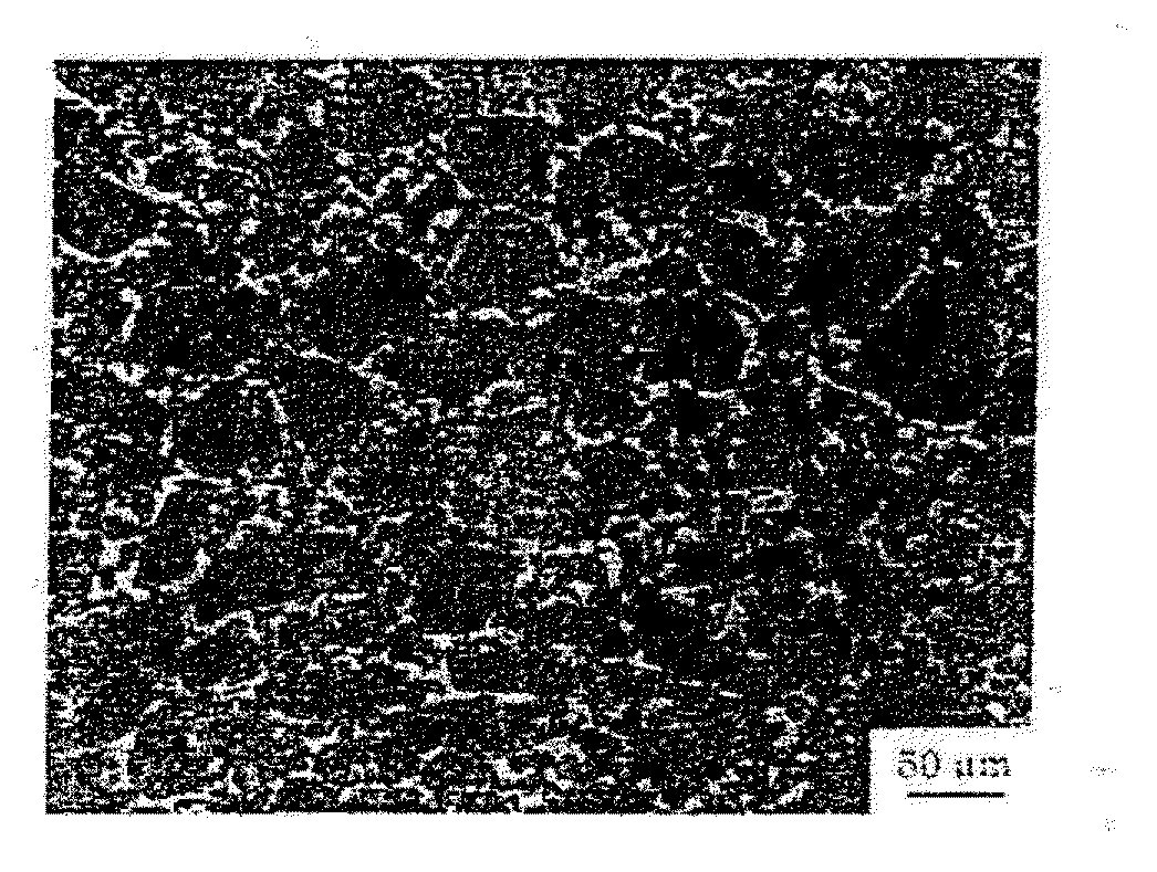
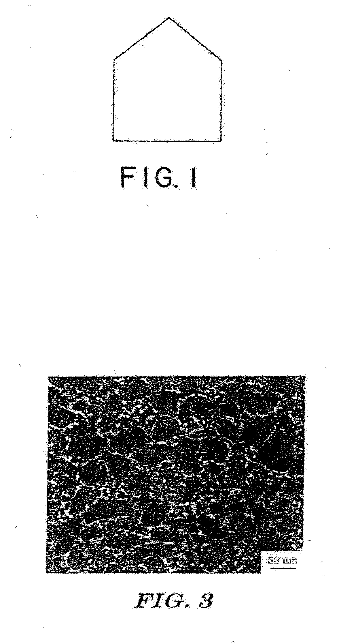
[0206]The technique of Example 1 was substantially repeated, except that no silicon carbide particulate was used in fabricating the preform, and the particle size distribution of the boron carbide was modified such that substantially all particles were smaller than about 45 microns. Following the pyrolysis step, the preforms contained about 75 percent by volume of the boron carbide particulate and about 4 percent by volume of carbon. This Example similarly is not part of the present invention.

[0207]After infiltration, the ceramic material contained nominally 75 vol. % B4C, 9 vol. % reaction-formed SiC, and 16 vol. % remaining Si (i.e., an Si / SiC / B4C composite). A polished section was examined using a Nikon Microphot-FX optical microscope. An optical photomicrograph of the material is shown in FIG. 3. It is clearly evident that, by careful selection of processing conditions, including addition of a source of boron to the silicon infiltrant, little growth and interlocking of the parti...

example 3

[0208]The technique of Example 2 was substantially repeated, except that, before supplying the silicon infiltrant to the lay-up, a monolayer of TETRABOR® boron carbide particulate (220 grit, ESK) was sprinkled onto the carbon cloth between the feeder rails. The amount of silicon was concomitantly increased to account for the added boron carbide, and to maintain an excess supply of silicon of about 10 percent, as in Example 1.


PUM

PropertyMeasurementUnit
diameteraaaaaaaaaa
temperatureaaaaaaaaaa

Abstract

A siliconized boron carbide composite material is made by infiltrating molten silicon metal into a porous mass including boron carbide. The porous mass contains little or no reactable carbon. The infiltration is designed and intended such that the infiltrant is substantially non-reactive with the constituents of the porous mass. The composite body so formed contains boron carbide and silicon metal, but substantially no silicon carbide formed in-situ from a reaction of the silicon metal with a carbon source. Such siliconized boron carbide composite materials have utility in armor applications.

Description

CROSS-REFERENCE TO RELATED APPLICATIONS[0001]This patent document is a Continuation-in-Part of U.S. patent application Ser. No. 13 / 412,418, filed on Mar. 5, 2012, which is a Continuation of U.S. patent application Ser. No. 12 / 150,597, filed on Apr. 28, 2008, which issued on Mar. 6, 2012 as U.S. Pat. No. 8,128,861, which is a Continuation-in-Part of U.S. patent application Ser. No. 11 / 433,056, now abandoned, filed on May 12, 2006, which claims the benefit of U.S. Provisional Patent Application No. 60 / 680,626, filed on May 12, 2005. Application Ser. No. 12 / 150,597 is also a Continuation-in-Part of U.S. patent application Ser. No. 11 / 185,075, filed on Jul. 19, 2005, which claims the benefit of U.S. Provisional Patent Application No. 60 / 623,485, filed on Oct. 30, 2004, and which U.S. Ser. No. 11 / 185,075 is a Continuation-in-Part of co-pending U.S. patent application Ser. No. 10 / 336,626, filed on Jan. 3, 2003, which is a Divisional of U.S. patent application Ser. No. 09 / 621,562, filed on...

Claims


Application Information

Patent Timeline
Patent Type & Authority Applications(United States)
IPC IPC(8): C04B35/573F41H5/04C04B41/50
CPCC04B35/573F41H5/0414C04B41/5096C04B35/563C04B35/80C04B41/009C04B41/85C04B2235/3821C04B2235/428C04B2235/5248C22C29/02C04B35/583C04B38/00C04B41/4523
Inventor AGHJANIAN, MICHAEL K.MCCORMICK, ALLYN L.MORGAN, BRADLEY N.LISZKIESICZ, JR., ANOTHONY F.RAMBERG, JEFFREY R.MCKENNA, DAVID W.
Owner AGHJANIAN MICHAEL K
Why Eureka
Try Eureka