
Method and Apparatus for Fabricating Boron Coated Straws for Neutron Detectors

a technology of boron coated straws and neutron detectors, which is applied in the direction of soldering apparatus, auxilary welding devices, instruments, etc., can solve the problems of large detection area, inability to achieve high-speed operation, and inability to meet the requirements of high-speed operation

Inactive Publication Date: 2014-04-24
PROPORTIONAL TECH
View PDF46 Cites 8 Cited by
  • Summary
  • Abstract
  • Description
  • Claims
  • Application Information

AI Technical Summary

Benefits of technology

The present invention is about an apparatus and process for making straw tubes used in manufacturing boron coated straw neutron detectors. The process involves creating a thin-walled straw by forming a foil with a boron coating into a cylindrical tube with a seam and then welding it, either by ultrasonic welding or by drawing it through a die to form a non-circular cross section, like a star-shaped cross section. This process allows for the efficient and reliable production of straw tubes for neutron detection.

Problems solved by technology

Unfortunately, the neutron detection systems of choice which utilizes pressurized tubes of 3He have several limitations.
While these systems can provide the needed spatial resolution and gamma ray discrimination, this technology cannot achieve high rate operation because of slow drift of positive ions.
Furthermore, large detection areas are costly, because of the complexity of the pressure vessels required, and parallax errors limit the time-of-flight accuracy of the instrument.
Perhaps the most problematic issue for the future of 3He detectors is a severe shortage of 3He.
Existing stockpiles of 3 He will soon be depleted and only limited amounts are naturally available or available from decay of U.S. and Russian tritium supplies.
Future instrument expansions will likely not afford the escalating cost of the dwindling 3He supply.
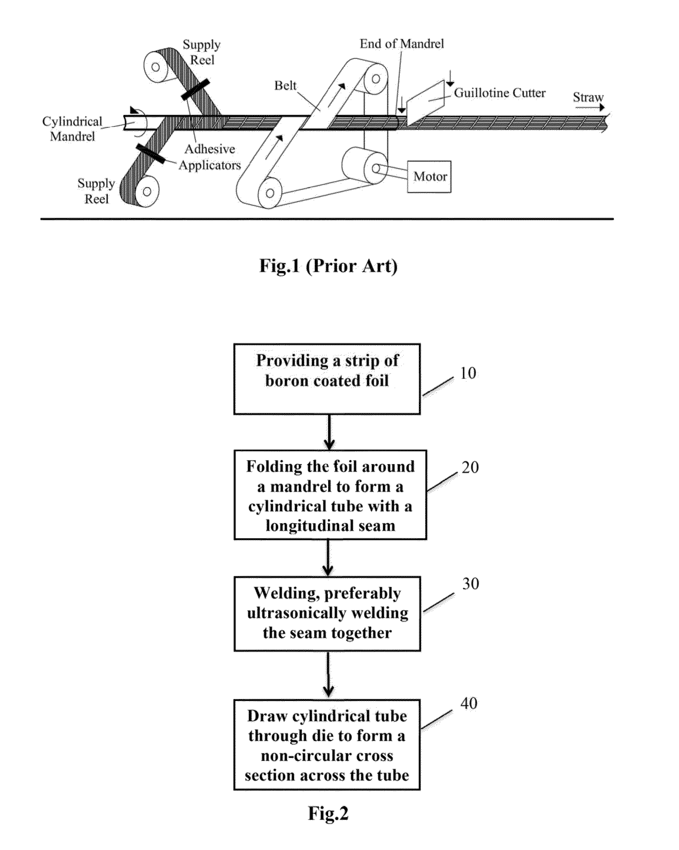
Initially, the adhesive utilized to bond the straw together could give off gases during operation and the outgas could interfere with detector performance.
Further, the temperature limits of the adhesive could also limit the conditions under which the detectors could operate.
Finally, boron-coated straws of the prior art formation were not readily shaped to have non-circular cross sections.

Method used


Image

  • Method and Apparatus for Fabricating Boron Coated Straws for Neutron Detectors
  • Method and Apparatus for Fabricating Boron Coated Straws for Neutron Detectors
  • Method and Apparatus for Fabricating Boron Coated Straws for Neutron Detectors

Examples


Embodiment Construction

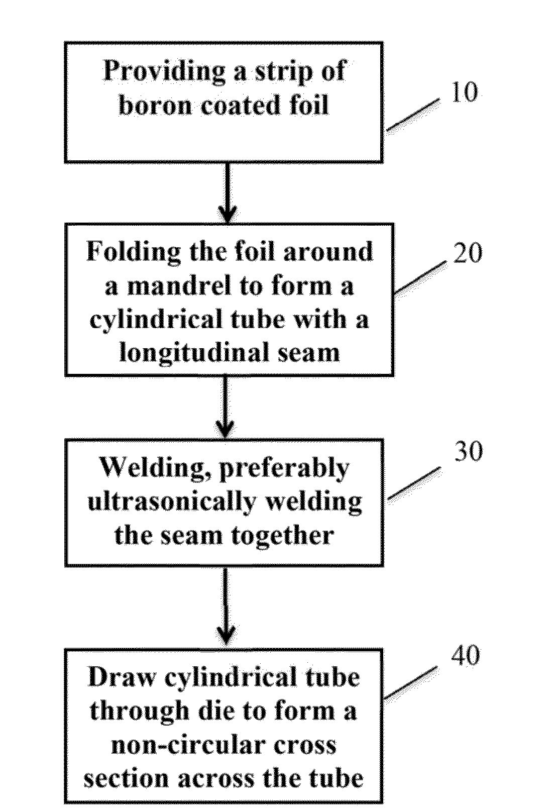
[0046]The present invention is an apparatus and a process for straw tube formation utilized in manufacturing boron coated straw neutron detectors. As shown in FIG. 2, in one embodiment, primarily utilized in a low volume production environment, the process involves a first step 10 of providing a strip of foil having a boron coating. Preferably, the strip of foil has a width slightly wider than the desired straw tube circumference. Generally, the strip will be about 0.02-0.04 inches wider than the desired circumference. In order that the foil substrate produce minimal loss of incident neutron flux and to permit ease of forming, thin foil having thickness 0.0005″-0.002″ is preferably employed. Formability can be further enhanced by annealing the foil in a vacuum oven. Typically, copper foil is annealed at 300° C. for about 8 hours while aluminum, depending on grade, can be done typically at 200° C. for 8 about hours. As will be appreciated, the width and length of the foil strip can b...


PUM

PropertyMeasurementUnit
diameteraaaaaaaaaa
non-circular shapeaaaaaaaaaa
diameteraaaaaaaaaa

Abstract

An apparatus and a process are disclosed for straw tube formation utilized in manufacturing boron coated straw neutron detectors. A preferred embodiment of the process for creating a thin walled straw for use in a boron-coated straw neutron detector comprises providing foil having a boron coating on a surface, forming the coated foil into a cylindrical tube having a longitudinal seam and the boron coated surface on the inside of the cylindrical tube, and then ultrasonically welding closed the seam of the tube. Optionally, the cylindrical tube can then be drawn through a die to form a straw tube having a non-circular cross section, preferably a star-shaped cross section.

Description

RELATED APPLICATIONS[0001]This application claims priority to U.S. Provisional Application No. 61 / 717,000 (“the '000 application”) filed Oct. 22, 2012. The '000 application is hereby incorporated by reference in its entirety for all purposes, including but not limited to, all portions describing the tube forming process of the present invention, those portions describing boron-coated straw detectors in general as background and for use as specific embodiments of the present invention, and those portions describing other aspects of manufacturing and testing of boron-coated straws that may relate to the present invention.GOVERNMENTAL SPONSORSHIP[0002]This invention was made with government support under DTRA01-02-D-0067 awarded by Defense Threat Reduction Agency and HSHQDC-12-C-00094 awarded by the Domestic Nuclear Detection Office. The government may have certain rights in the invention.REFERENCE TO A SEQUENTIAL LISTING[0003]Not applicable.BACKGROUND OF THE INVENTION[0004]1. Field of...

Claims


Application Information

Patent Timeline
Patent Type & Authority Applications(United States)
IPC IPC(8): B23K31/02G01T3/00
CPCG01T3/008B23K31/027B21C37/0818B21C37/09B65H18/103B65H2301/51145C23C14/021C23C14/025C23C14/0635C23C14/165C23C14/562
Inventor LACY, JEFFREY L.
Owner PROPORTIONAL TECH
Learn More