
Stimulating bone growth and controlling spinal cord pain

a technology of stimulating bone growth and spinal cord pain, applied in the field of stimulating bone growth and controlling spinal cord pain, can solve the problems of unnecessary surgical removal of implants, achieve the effects of promoting bone growth, reducing the incidence of non-union healing, and improving the healing of fractured bones

Inactive Publication Date: 2014-04-24
KIM KEUN YOUNG ANTHONY
View PDF19 Cites 17 Cited by
  • Summary
  • Abstract
  • Description
  • Claims
  • Application Information

AI Technical Summary

Benefits of technology

The present invention describes a way to use a biomechanical spacer or cage that is lined with conductive metal or polymer strips (specifically, gold) to stimulate bone growth and reduce the incidence of non-union healing. The conductive metal strips interact with an external electric field to create a direct electric current, which promotes bone growth and results in improved healing of fractured bones. This method does not require surgical removal of the implant and has a higher success rate for complete bone fusion, especially for patients at high risk for non-union healing.

Problems solved by technology

Because the present implants do not contain batteries, surgical removal of the implant is unnecessary.

Method used


Image

  • Stimulating bone growth and controlling spinal cord pain
  • Stimulating bone growth and controlling spinal cord pain

Examples


example 1

Femur Fusion

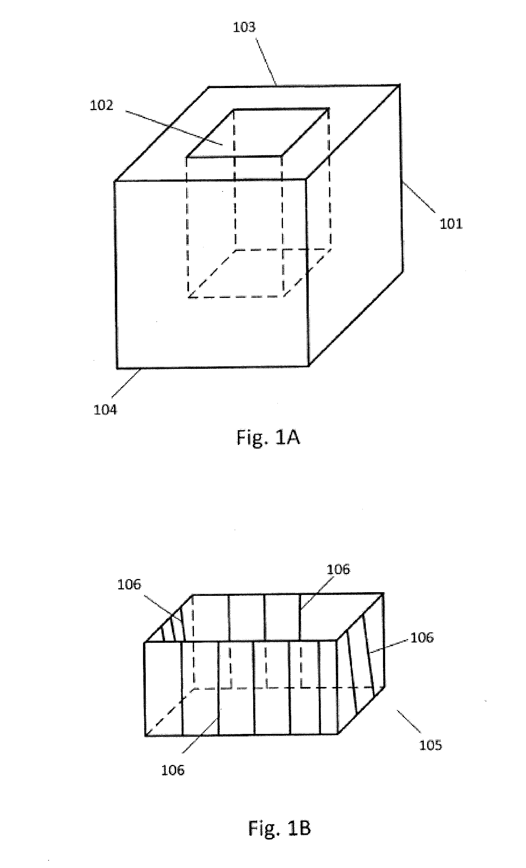
[0035]A human patient presents with a broken femur. A mechanical spacer / cage shown in FIGS. 1A and 1B is surgically implanted between the proximal and distal femur so that the cage abuts the distal femur and the proximal femur. The interior of the cage contains a plurality of gold strips that run from the proximal femur to the distal femur and an osteoconductive scaffolding material such as autologous bone. The patient is given a leg band or wrap to wear around the femur adjacent to where the implant is located. The leg band / wrap emits an electromagnetic field which produces a current in the gold strips resulting in bone formation and resulting in a fully healed union between the distal femur and the proximal femur.

[0036]Additional surgical procedures are performed using the implants of the present invention to repair non-union long bone fractures. Non-union podiatry fractures, non-union spinal fractures and skull fractures with cranioplasty.

The present invention can add...


PUM


Abstract

Bone growth for fusion promotion is stimulated in a mammalian patient in need thereof. Bone growth stimulation is achieved by implanting an electro-conductive bone growth stimulating implant in a region in the patient where bone growth is desired. An external device is worn by the patient to produce a direct current in the implant whereby bone growth is stimulated. The external device produces a magnetic field that induces an electric current in the implant. The electric current stimulates bone growth. The implant contains strips of a biocompatible conductive metal, such as, for example, nickel, gold or titanium. The strips can also be made of a conductive polymer such as for example, graphene. Implants to treat spinal cord pain are also disclosed.

Description

CROSS-REFERENCE TO RELATED APPLICATION[0001]The present application claims priority under 35 U.S.C. §119(e) to U.S. Provisional Application No. 61 / 743,683, filed on Sep. 10, 2012, the disclosure of which is incorporated herein by reference in its entirety.FIELD OF THE INVENTION[0002]The present invention relates to methods stimulating bone growth, methods of controlling pain and implants and devices to conduct said methods. In particular, implants containing electro-conductive strips are implanted in a mammalian patient in regions of the body to promote bone growth. An external device is used to produce an electric current along the electro-conductive material wherein the electric current promotes bone growth along the path of the current. Additionally, implants containing electro-conductive strips are implanted in a mammalian patient in regions adjacent to the spinal cord for pain control. An external device is used to produce an electric current along the electro-conductive strips...

Claims


Application Information

Patent Timeline
IPC IPC(8): A61N1/32
CPCA61N1/326A61N1/0468A61N1/3787A61N1/0464A61L27/047A61L27/3608A61L2430/02A61N2/008A61N2/06
Inventor KIM, KEUN-YOUNG ANTHONY
Owner KIM KEUN YOUNG ANTHONY
Learn More