

Rotating electrical machine
- Summary
- Abstract
- Description
- Claims
- Application Information
AI Technical Summary
Benefits of technology
Problems solved by technology
Method used
Image

Examples
Embodiment Construction
[0044]In the following, the present invention will be described with reference to the accompanying drawings.
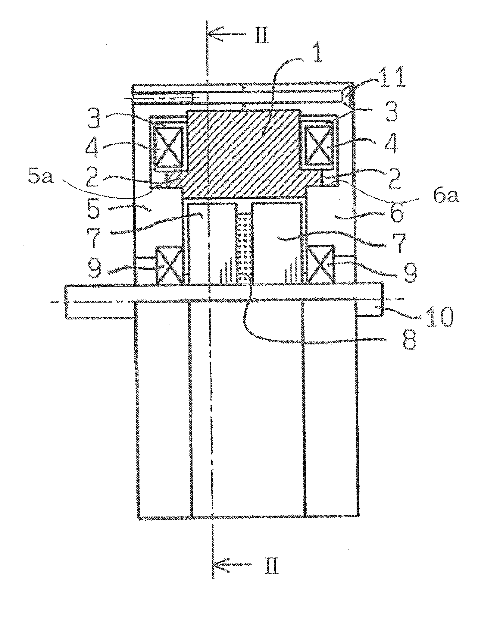
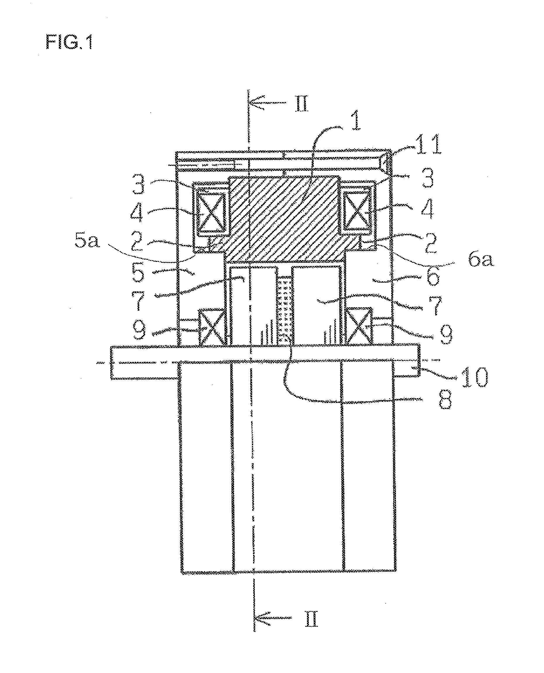
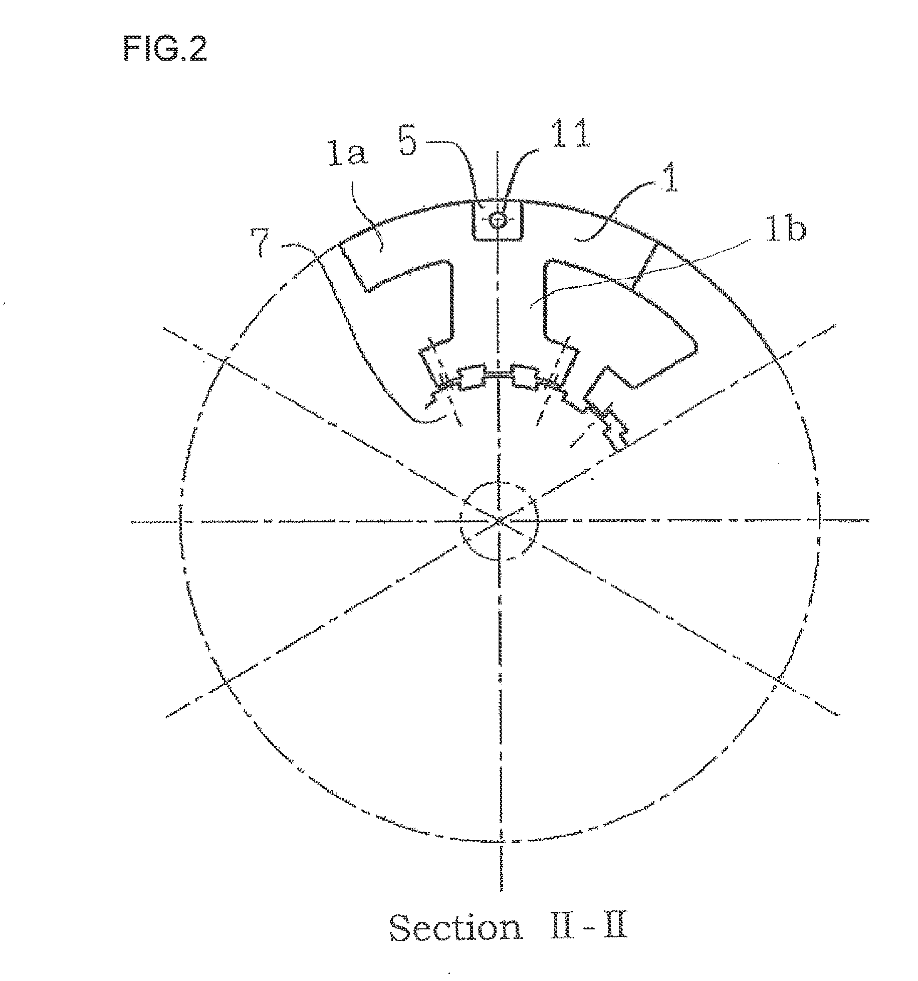
[0045]FIG. 1 shows an example of a configuration according to the present invention, and is a sectional view including a rotation axis center of a HBSTM according to the present invention. FIG. 2 is a sectional view which is seen from the direction of the rotation axis center of FIG. 1 and which is taken along line II-II of FIG. 1.
[0046]In FIG. 1 and FIG. 2, reference numeral 1 denotes a stator formed of dust cores. Further, reference numeral 2 denotes a flange-like stator side guide portion which is made to project in the shaft direction from the stator 1 and which is formed to have a circular arc shape concentric with the inner diameter of the stator 1. The dust core is manufactured in such a manner that, by mixing soft magnetic iron powder with a small amount of resin as a lubricant or binder, the iron power particles are coated with the resin so that electrical insulation ...
PUM
 Abstract
Description
Claims
Application Information