
Friction stir welding tool with shoulders having different areas; methods using such tool; product welded with such tool

a technology of friction stir and shoulder, which is applied in the direction of manufacturing tools, soldering devices, auxillary welding devices, etc., can solve the problems of inferior quality of joints, increased labor intensity, and inapplicability of known conventional fsw tools, so as to increase the production rate, increase the specific strength-to-weight ratio, and increase the heat input

Active Publication Date: 2014-05-01
SAPA
View PDF5 Cites 12 Cited by
  • Summary
  • Abstract
  • Description
  • Claims
  • Application Information

AI Technical Summary

Benefits of technology

The invention is a method and tool for welding extruded profiles together to create a strong and lightweight joint. The weld has a triangular shape, which increases strength and prevents bending loads. The tool has asymmetrical shoulders, which allow for increased heat input and faster production rates. The method can be used to weld double skin panels, tubes, and other curved surfaces. The tool is small and can be inserted into limited spaces, eliminating the need for an external support. The invention also provides a friction stir welding tool with asymmetrical contact surfaces that control the motion of the plasticized material. The method and tool allow for efficient and profitable welding.

Problems solved by technology

The plasticized material tends to run-off from the weld zone under process loads, which in turn might lead to formation of internal or surface breaking defects in the joint.
In case of other configurations of the work pieces than flat ones, e.g. with a limited access and space for the support from the bottom of the weld zone between the inclined inner triangular walls as illustrated here, the known conventional FSW tools are not applicable.
In such instances fusion welding techniques are often called upon which produce joints with inferior quality and are more generally less productive especially for thicker section welding.
However a symmetrical triangular shape of the profile providing the best load force distribution through the welded panel is then not achievable.
For example, this problem appears in manufacturing of so called double skin panels from multi-void hollow extrusions or profiles made of aluminum alloy material by joining extrusions with FSW method into the double skin panels, having beneficial strength-to-weight ratio.
This solution has the disadvantage of forming crack-like notches in the vicinity of the weld which adversely affects fatigue performance of the construction.
Besides that, moisture can accumulate in the crack between the faying surfaces and lead to accelerated corrosion in the welded section, and thus weaker construction.
Furthermore, such profile construction does not provide the regular symmetrical triangular shape in the cross section view of the extruded profile for the optimal exploitation of load distribution within the welded panel, which makes the panel susceptible to bending moments and shearing within some of the final welded panel areas.
However, the tool of JP 2007-253210 cannot be used to weld the opposite flat portion at the tapered end of the triangular space formed between the profiles to be joined, due to lack of access space for the tool between the inclined inner walls.
While this is generally desirable, the solution has an inherent limitation that the above described advantageous triangulation design of inner walls that provides the best load distribution is not achievable by hitherto available equipment, because of the limited space available for an FSW tool shoulder in the desired welding zone.
A tool with symmetrical shoulders small enough to fit into such limited space between the inclined triangular inner walls would have the disadvantage of providing a limited heat input for plasticizing the material, which would result in low productivity due to low process speed (or linear movement of the tool) that would not be profitable.
As stated above this would subject the panel to a bending moment and would thus limit the strength of the welded final product.
However, in this case the contact surface configuration directs the material flow from the center part to the shoulder periphery as illustrated in FIG. 5 of JP2002-263863, and thus the material might escape which can lead to a weld joint of inferior strength and increased corrosion risk.
Another FSW tool and method is illustrated in JP2004-216435, where the upper and lower shoulders are rotated in opposite directions due to tool design which requires very complicated equipment and results in a rather poor welding seam due to intensive mixing of the plasticized material rotated by both shoulders in the opposite directions.
A tool of this type cannot be used for welding limited space configurations for the reasons described above.
This results in longer time to crack initiation under cyclic loading.

Method used


Image

  • Friction stir welding tool with shoulders having different areas; methods using such tool; product welded with such tool
  • Friction stir welding tool with shoulders having different areas; methods using such tool; product welded with such tool
  • Friction stir welding tool with shoulders having different areas; methods using such tool; product welded with such tool

Examples


Embodiment Construction

[0056]The invention will now be described in details by referring to the appended drawings. Corresponding elements of the different embodiments have the same reference numerals. It is to be understood that the scope of the invention is not limited to the embodiments as shown in the appended Figures which are used only for clarification purpose.

[0057]The reference numerals in the drawing indicate:

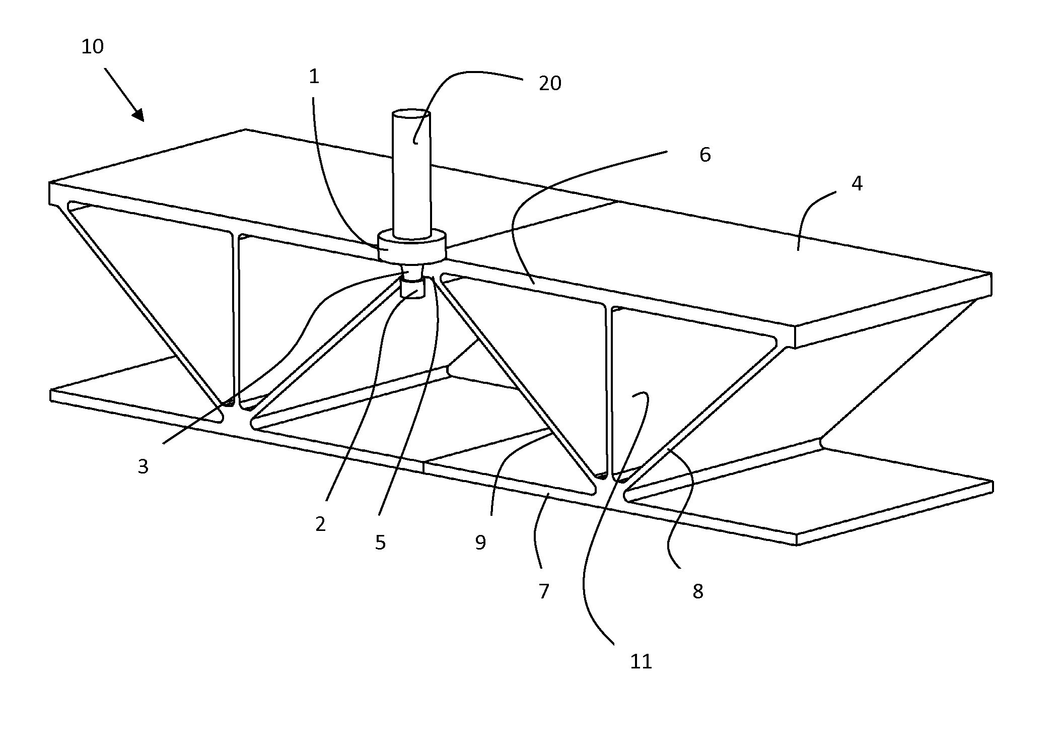
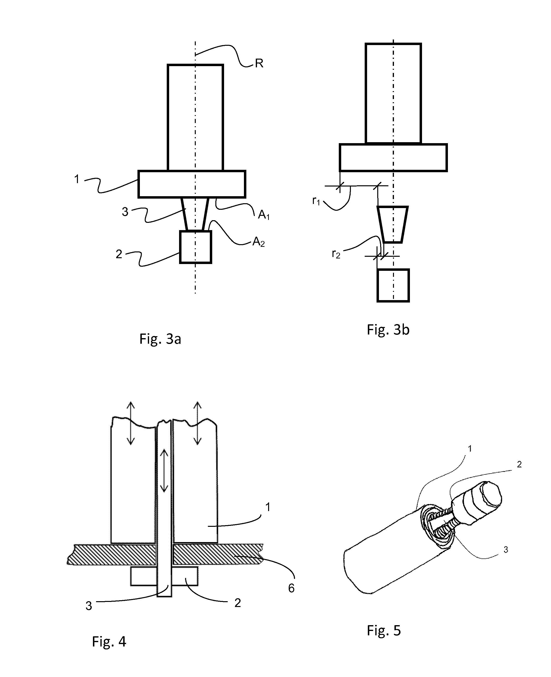
[0058]1 first shoulder

[0059]2 second shoulder

[0060]3 pin

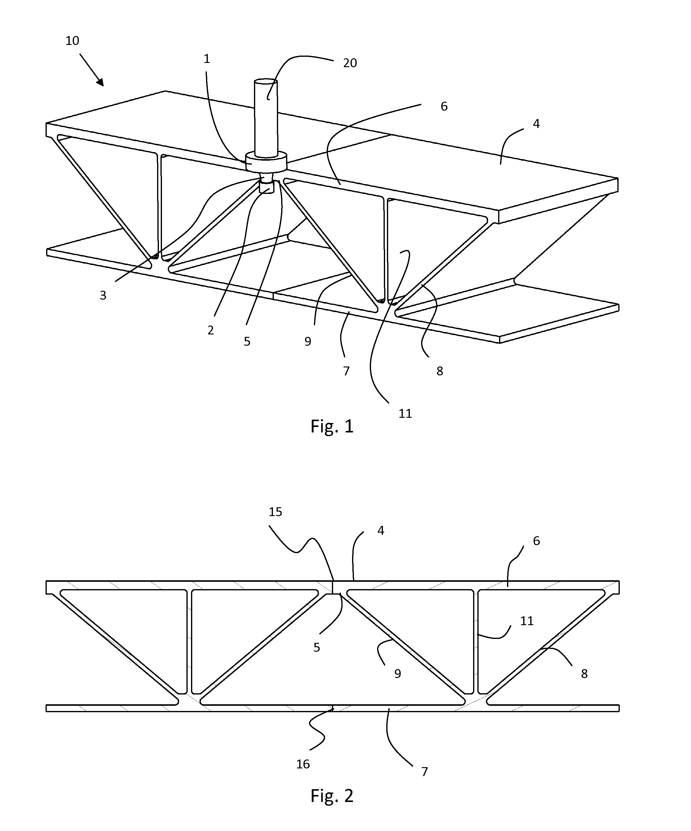
[0061]4 first surfaces of first portions 6 of the work pieces

[0062]5 opposite surfaces of first portions 6

[0063]6 first portions of the work pieces

[0064]7 second portions of the work pieces

[0065]8 inclined inner wall

[0066]9 inclined inner wall

[0067]10 work piece

[0068]11 central inner wall

[0069]15 joint between flat portions 6

[0070]16 joint between flat portions 7

[0071]17 narrowing portion in joint 15

[0072]20 FSW tool

[0073]FIG. 1 shows a cross-sectional view of a two adjacent and abutting hollow extrusion profiles 10, which are being joi...


PUM

PropertyMeasurementUnit
speedaaaaaaaaaa
thicknessaaaaaaaaaa
thicknessaaaaaaaaaa

Abstract

The present application relates to a friction stir welding tool (20) for joining two adjacent work pieces (10), which work pieces comprise portions (6) to be welded and having a narrow space there between on one side, said tool having an axis of rotation, and comprising a first shoulder (1), a second shoulder (2), and a pin (3) arranged so as to connect the first and second shoulders, wherein said first shoulder has a first contact surface for friction heat generation to the work pieces to be joined during welding, said first contact surface having a first contact area, and said second shoulder has a second contact surface for friction heat generation to an opposite surface (5) of the same portions of the work pieces to be joined, said second contact surface having a second contact area, the first and second areas having different sizes, where the first area is a larger sized area than the second area. The application also relates to a method of joining work pieces, a product comprising joined pieces, and the use of such friction stir welding tool.

Description

TECHNICAL FIELD [0001]The present invention pertains to a friction stir welding tool, a method of joining work pieces, particularly having a complicated geometry, to a product comprising joined pieces, and the use of friction stir welding tool with improved access ability in narrow spaces and higher productivity.BACKGROUND OF THE INVENTION[0002]It is known in the art to use a friction stir welding (FSW) for joining of two metal or plastic work pieces. In essence, FSW employs a non-consumable rotating tool, which interacts with the work pieces by its contacting surfaces to generate frictional heating and thus plasticizes the material in a weld zone. Local softening of the material in the weld zone facilitates mixing of material from the work pieces and upon translation of the tool along the welding direction the joint is formed. The plasticized material tends to run-off from the weld zone under process loads, which in turn might lead to formation of internal or surface breaking defec...

Claims


Application Information

Patent Timeline
Patent Type & Authority Applications(United States)
IPC IPC(8): B23K20/12B29C65/06
CPCB23K20/1255B29C65/0672B23K20/1225B23K20/126B23K2101/006B23K2101/045B23K2101/18B23K2103/10Y10T403/477
Inventor OSIKOWICZ, WOJCIECH
Owner SAPA
Learn More