Fourier Ptychographic X-ray Imaging Systems, Devices, and Methods

a ptychographic and x-ray imaging technology, applied in the field of wide field of view and high-resolution digital imaging techniques, can solve the problems of compromising image resolution and field of view, limiting the output of a conventional imaging platform (e.g., microscope), and reducing the range of view

Active Publication Date: 2014-05-08
CALIFORNIA INST OF TECH
View PDF6 Cites 65 Cited by
  • Summary
  • Abstract
  • Description
  • Claims
  • Application Information

AI Technical Summary

Benefits of technology

[0184]Embodiments of the invention may provide one or more of the following technical advantages. Some examples of these advantages are provided below.

Problems solved by technology

The throughput of a conventional imaging platform (e.g., microscope) is generally limited by the space-bandwidth product defined by its optical system.
Prior attempts to increase space-bandwidth product of conventional microscopes have been confounded by the scale-dependent geometric aberrations of their objective lenses, which results in a compromise between image resolution and field-of-view.
Increasing the space-bandwidth product of conventional imaging platforms may be limited by: 1) scale-dependent geometric aberrations of its optical system, 2) constraints of the fixed mechanical length of the relay optics and the fixed objective parfocal length, and / or 3) availability of gigapixel digital recording devices.
These previous attempts to increase spatial-bandwidth product using interferometric synthetic aperture techniques have limitations.
As such, the reconstructed images tend to suffer from various coherent noise sources, such as speckle noise, fixed pattern noise (induced by diffraction from dust particles and other optical imperfections in the beam path), and multiple interferences between different optical interfaces.
Another limitation is that interferometric imaging may be subjected to uncontrollable phase fluctuations between different measurements.
Another limitation is that previously reported attempts require mechanical scanning, either for rotating the sample or for changing the illumination angle.
In terms of the spatial-bandwidth product, these systems present no advantage as compared to a conventional microscope with sample scanning and image stitching.
Another limitation is that previous interferometric synthetic aperture techniques are difficult to incorporate into most existing microscope platforms without substantial modifications.
Furthermore, color imaging capability has not been demonstrated on these platforms.
These complex components can be expensive to fabricate and difficult to use.
For example, conventional digital in-line holography does not work well for contiguous samples and contact-imaging microscopy requires a sample to be in close proximity to the sensor.

Method used


Image

  • Fourier Ptychographic X-ray Imaging Systems, Devices, and Methods
  • Fourier Ptychographic X-ray Imaging Systems, Devices, and Methods
  • Fourier Ptychographic X-ray Imaging Systems, Devices, and Methods

Examples


Embodiment Construction

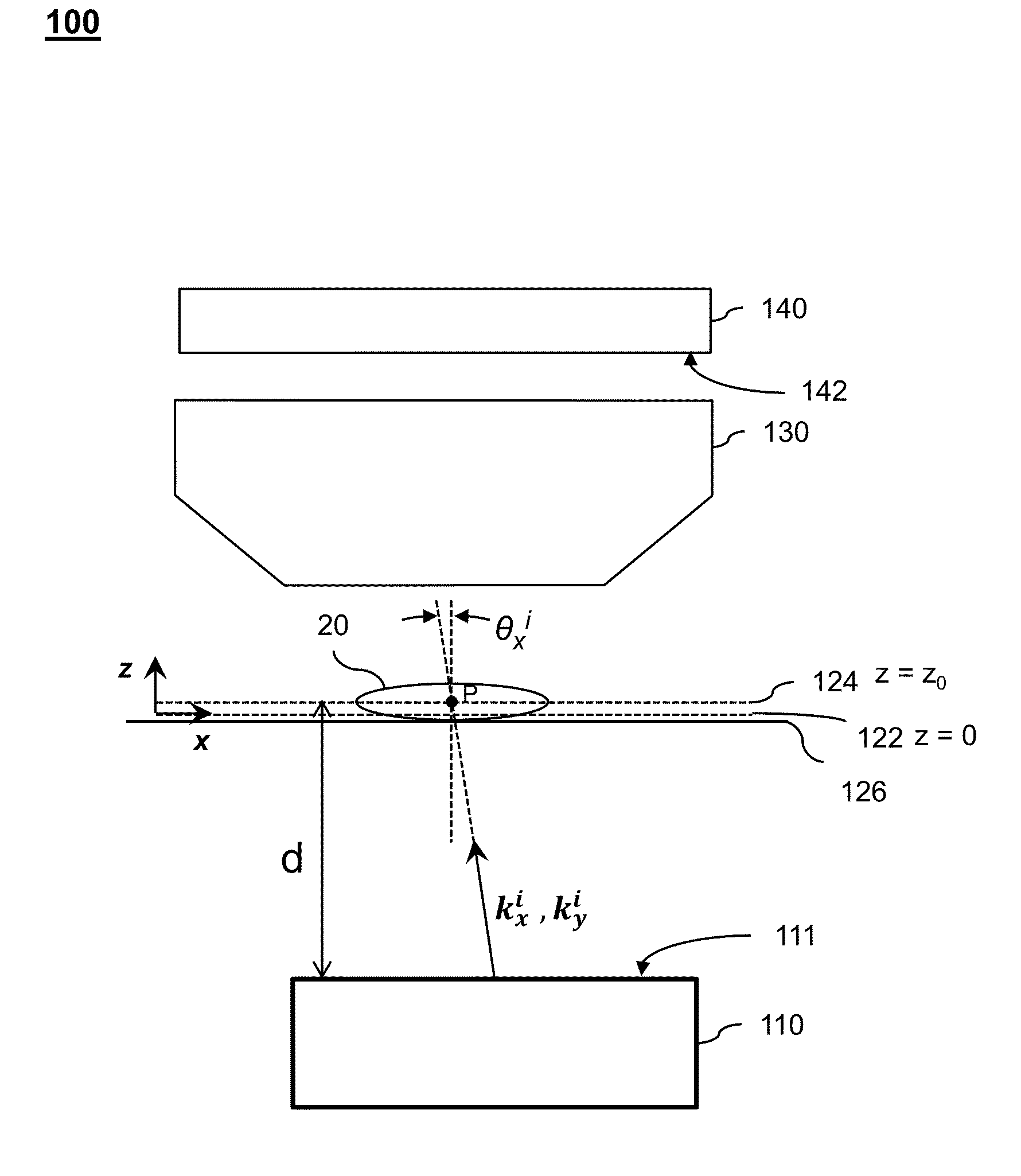
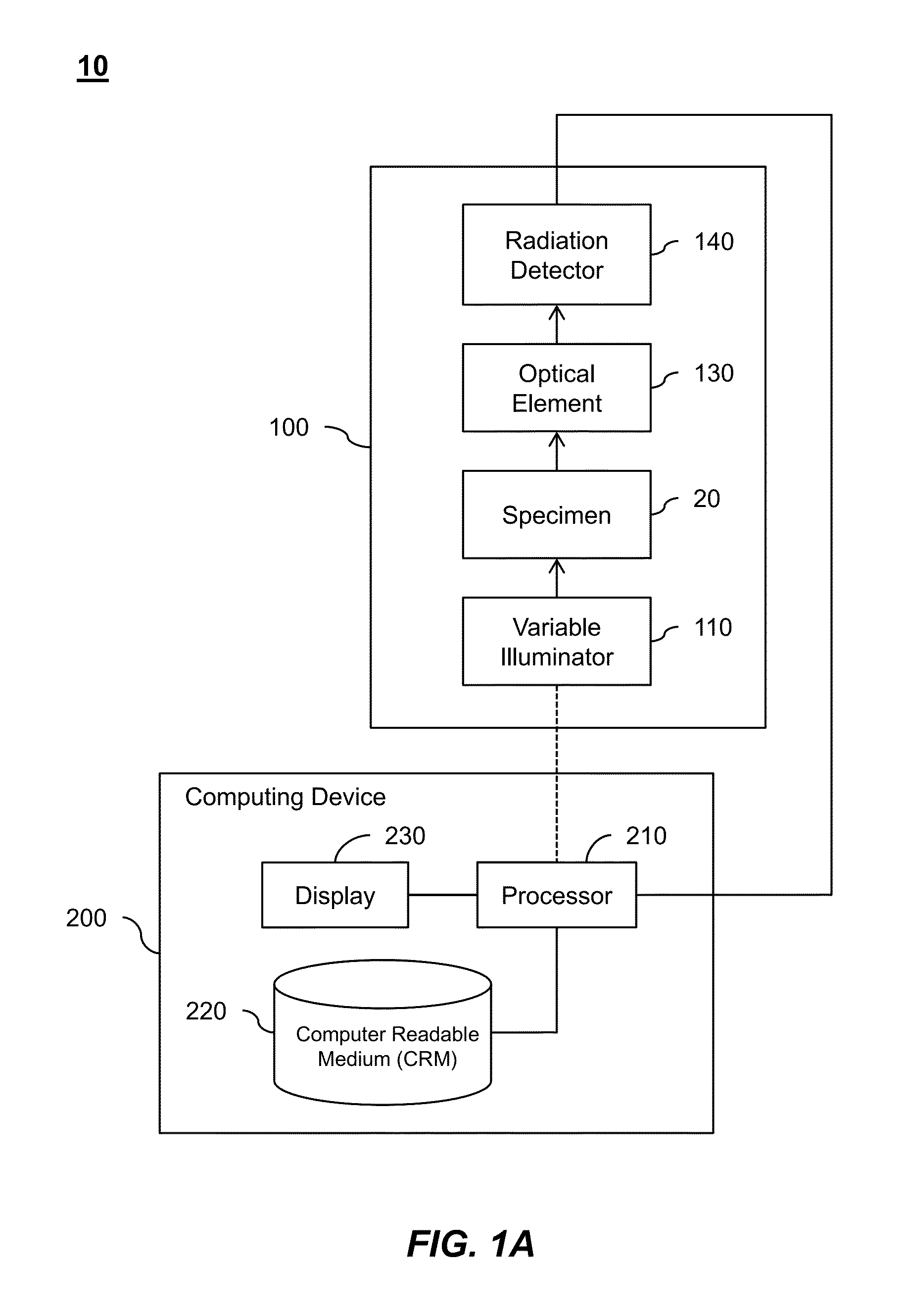
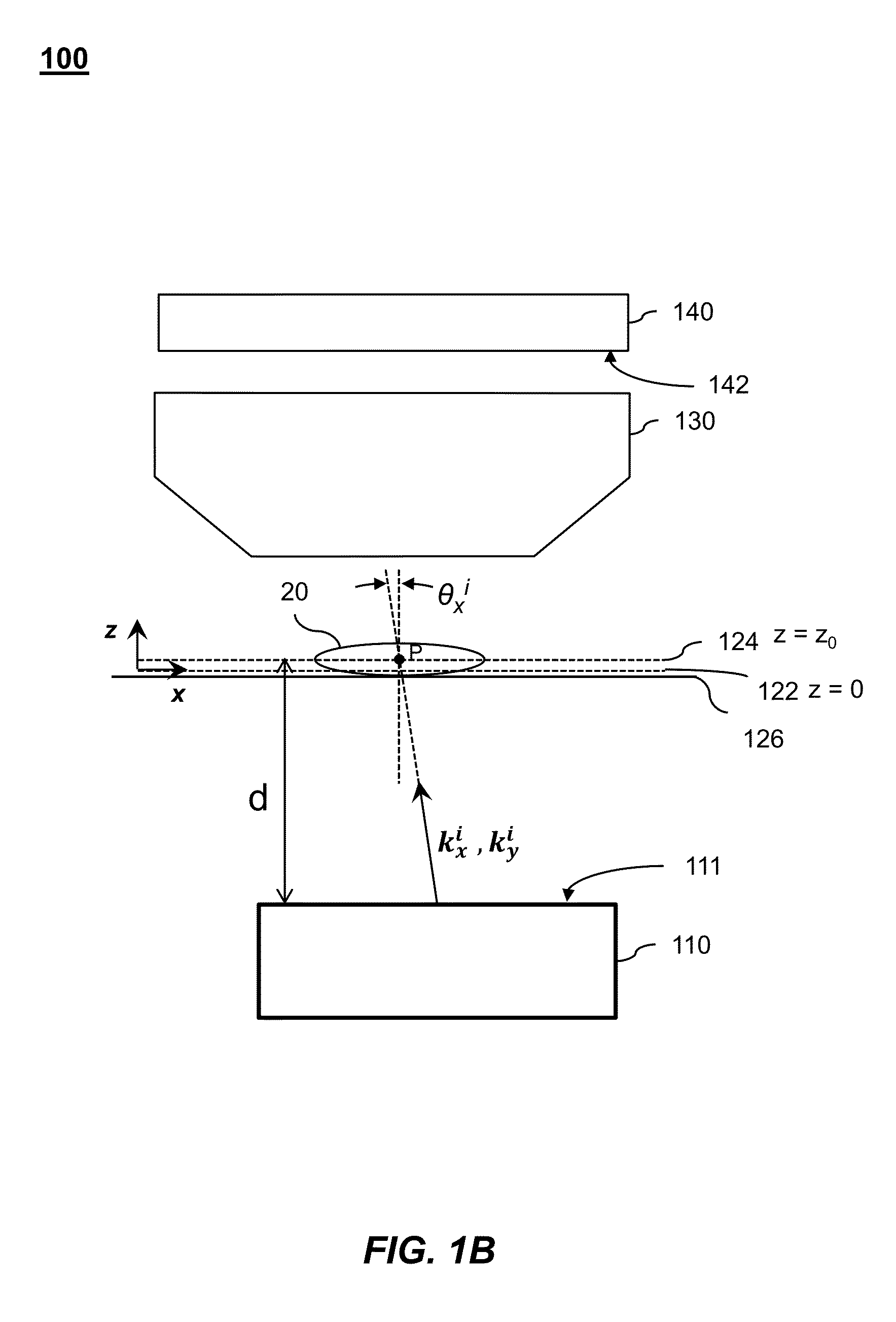
[0052]Embodiments of the present invention will be described below with reference to the accompanying drawings. Although embodiments of FPI systems, devices, and methods may be described herein with respect to illumination with visible light radiation, these FPI systems, devices, and methods may also be used with other forms of radiation such as, for example, acoustic waves, Terahertz waves, microwaves, and X-rays.

[0053]Some embodiments include an FPI system comprising a variable illuminator, optical element, radiation detector, and a processor. The variable illuminator successively illuminates a specimen being imaged with plane waves at a plurality of N different incidence angles. The optical element filters light issuing from the specimen. The optical element may be, for example, an objective lens that accepts light issuing from the specimen based on its numerical aperture. In some cases, the optical element may be a low numerical aperture objective lens that provides a correspond...


PUM


Abstract

Methods, systems, and devices of Fourier ptychographic X-ray imaging by capturing a plurality of variably-illuminated, low-resolution intensity X-ray images of a specimen and computationally reconstructing a high-resolution X-ray image of the specimen by iteratively updating overlapping regions in Fourier space with the variably-illuminated, low-resolution intensity X-ray images.

Description

CROSS-REFERENCES TO RELATED APPLICATIONS[0001]This is a non-provisional application of, and claims priority to, U.S. Provisional Patent Application No. 61 / 720,258 entitled “Breaking the Spatial Product Barrier via Non-Interferometric Aperture-Sythesizing Microscopy (NAM),” filed on Oct. 30, 2012 and to U.S. Provisional Patent Application No. 61 / 847,472 entitled “Fourier Ptychographic Microscopy,” filed on Jul. 17, 2013. These provisional applications are hereby incorporated by reference in their entirety for all purposes.[0002]This non-provisional application is related to the following co-pending and commonly-assigned patent application, which is hereby incorporated by reference in its entirety for all purposes:[0003]U.S. patent application Ser. No. 14 / 065,280, entitled “Fourier Ptychographic Imaging Systems, Devices, and Methods,” filed on Oct. 28, 2013.BACKGROUND OF THE INVENTION[0004]Embodiments of the present disclosure generally relate to wide field-of-view, high-resolution di...

Claims


Application Information

Patent Timeline
Patent Type & Authority Applications(United States)
IPC IPC(8): G21K7/00
CPCG21K7/00G02B21/002G02B21/365G02B21/367G02B27/58G06V20/693
Inventor ZHENG, GUOANYANG, CHANGHUEIHORSTMEYER, ROARKE
Owner CALIFORNIA INST OF TECH
Why Eureka
Try Eureka