Indented Mold Structures For Diamond Deposited Probes

a technology of diamond deposited probes and molds, applied in the field of nanostructures, can solve the problems of reducing the young's modulus, weakening the material, time-consuming and often cost prohibitive modification process

Inactive Publication Date: 2014-05-08
RAVE
View PDF1 Cites 6 Cited by
  • Summary
  • Abstract
  • Description
  • Claims
  • Application Information

AI Technical Summary

Problems solved by technology

This ion implantation creates defects in the deposited material that can reduce the Young's modulus and weakening the material.
Furthermore, the modification process is time consuming and often cost prohibitive especially if large volumes of probes are required for a particular application.
Although using EB alleviates the ion implantation issue, it does not address the probe apex dulling issue.
In addition, the process would be very slow without a chemically assisted etching process which can be difficult to apply to some crystalline materials like diamond and boron nitride.
Again, this technique must be done on probe by probe basis leading to the same disadvantages associated with the modification of probes using FIB.
Laser ablation is another technique

Method used


Image

  • Indented Mold Structures For Diamond Deposited Probes
  • Indented Mold Structures For Diamond Deposited Probes
  • Indented Mold Structures For Diamond Deposited Probes

Examples


Embodiment Construction

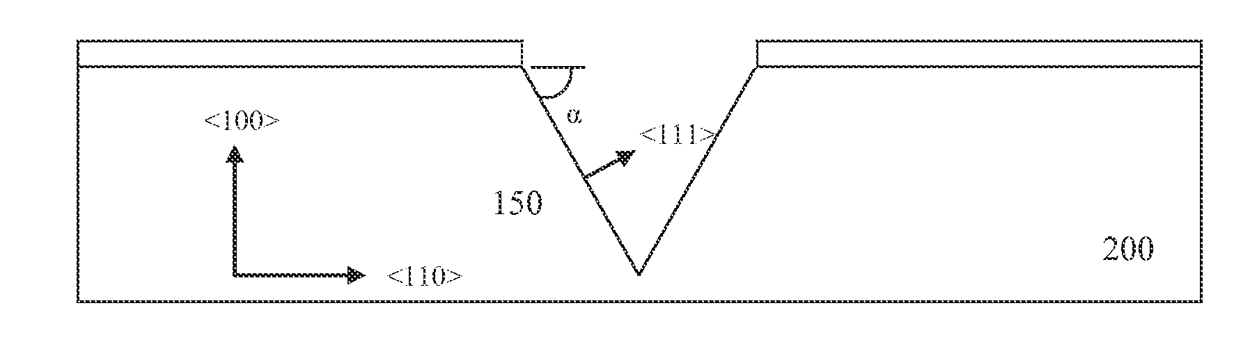
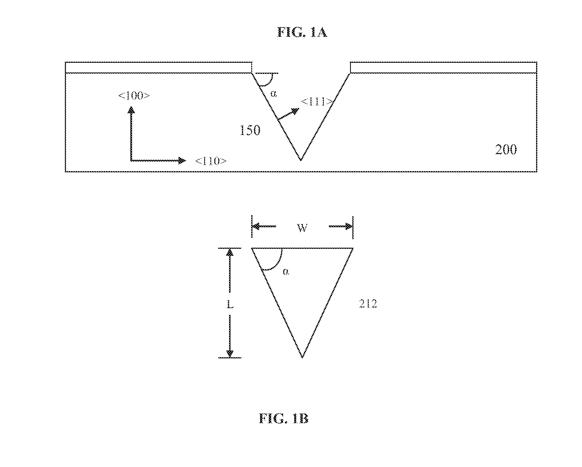
[0042]The present invention discloses a novel method of fabricating a SPM probe. The SPM probe 250 includes a planar body 230, a cantilever 225 extending from an edge of the body 230, and a tip 212 depending from an end of the cantilever 225, having a length and a width.

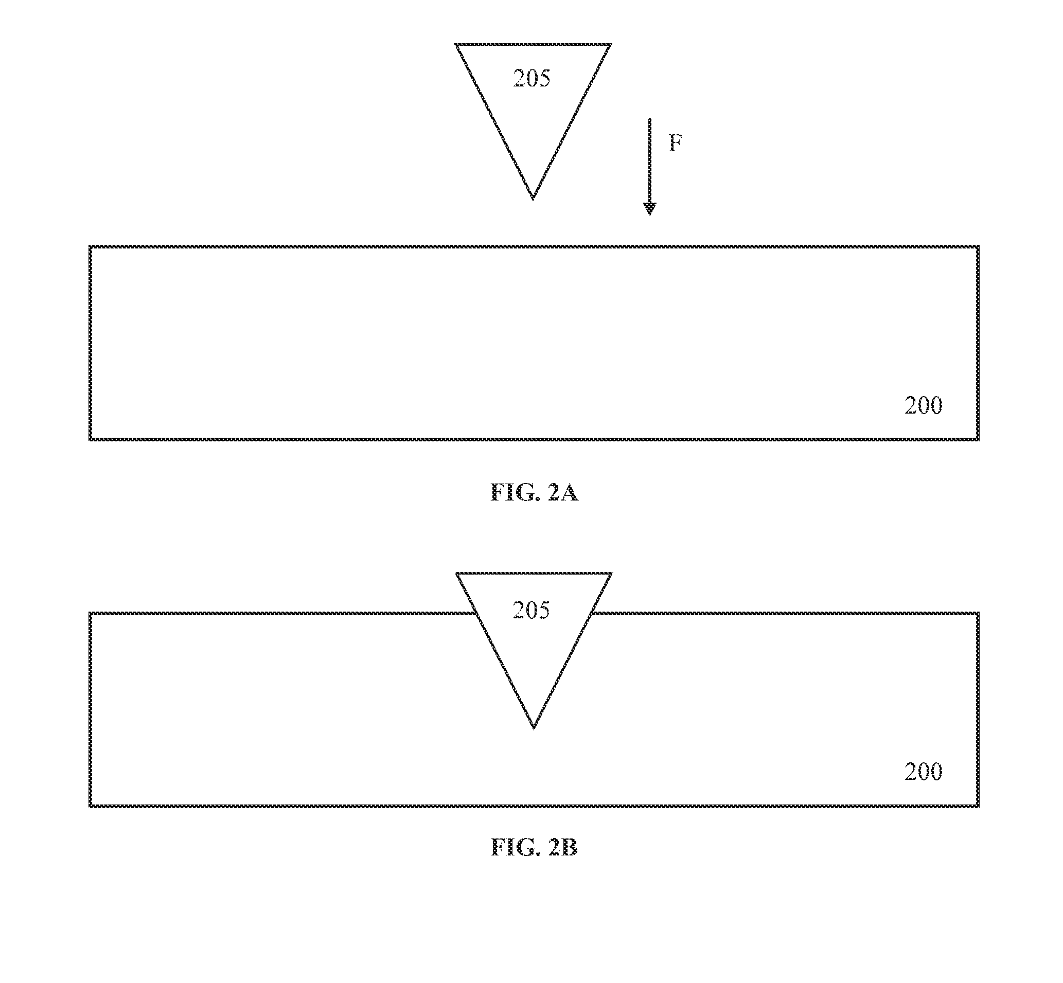
[0043]The method of fabricating the SPM probe 250 comprises the steps of: (a) positioning a pattern probe 205 over a mold substrate material 200; (b) indenting the pattern probe 205 into the mold substrate material 200 such that a mold pit 210 is formed in the shape of the pattern probe 205; (c) depositing a film 215 onto the mold substrate material 200 such that the mold pit 210 is filled with the deposited film 215; (d) removing a portion of the deposited 215 film to form the probe 250; and (e) releasing the probe 250 from the mold substrate material 200.

[0044]The mold substrate material 200 can vary greatly depending on the pattern probe 205 being used to create the shape of the mold pit 210. Very soft materials l...


PUM


Abstract

The present invention discloses a method of fabricating a scanning probe microscopy probe including positioning a pattern probe over a mold substrate; indenting the pattern probe into the mold substrate material to form a mold pit; depositing a film onto the mold substrate including the mold pit; removing a portion of the deposited film to form a probe, and releasing the probe from the mold substrate material.

Description

FIELD OF THE INVENTION[0001]The present invention relates generally to nanostructures and more specifically to methods of fabricating a probe for use in applications such as scanning probe microscopy, material hardness testing and nanomachining.BACKGROUND OF THE INVENTION[0002]Fabrication of high aspect ratio scanning probe microscopy (SPM), where SPM encompasses the following: Atomic Force Microscopy (AFM), Scanning Tunneling Microscopy (STM), Lateral Force Microscopy (LFM), Magnetic Force Microscopy (MFM) and Near-field Scanning Optical Microscopy (NSOM) and many others more obscure types not listed, probes via deposition processes requires a high aspect molded structure, from this point forward referred to as the mold or mold pit, to be filled by the material being deposited. The mold must meet two distinct criteria: 1) the mold must have a small probe radius or a sharp point at its apex and 2) the mold must have an aspect ratio that meets the need of the application.[0003]For lo...

Claims


Application Information

Patent Timeline
IPC IPC(8): G01Q70/16G01Q70/08
CPCG01Q70/08G01Q70/16G01Q70/14
Inventor BRINKLEY, DAVIDWHITE, ROY L.
Owner RAVE
Why Eureka
Try Eureka