
Nanotube cantilever probes for nanoscale magnetic microscopy

a nanotube and magnetic microscopy technology, applied in the field of microdimensional analytical probes for magnetic force microscopy and magnetic resonance force microscopy, can solve the problems of inability to use present cantilevers, difficult optical detection, and inability to detect single proton and single electron spin

Inactive Publication Date: 2005-05-03
BOSTON COLLEGE
View PDF6 Cites 41 Cited by
  • Summary
  • Abstract
  • Description
  • Claims
  • Application Information

AI Technical Summary

Benefits of technology

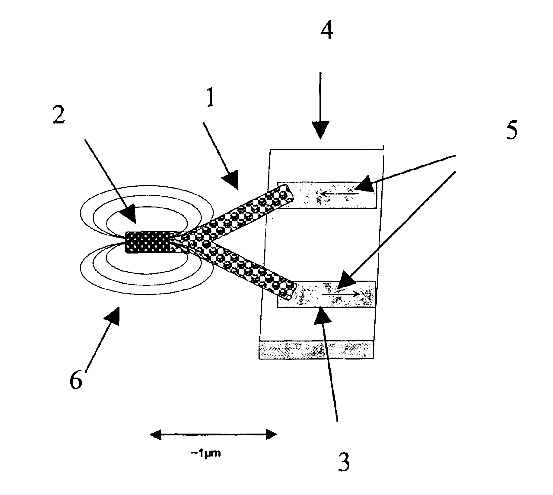
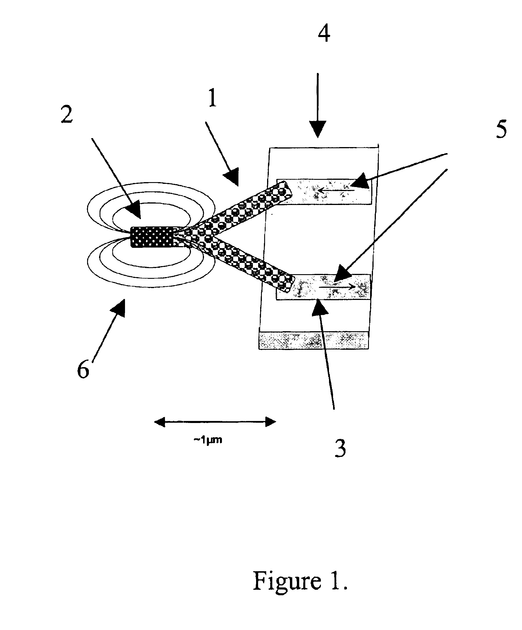
[0011]Carbon nanotubes (hereinafter referred to as CNTs) offer significant advantages in that they possess piezoelectric properties. The piezoelectric properties allow a means of internally detecting the movement of a cantilever comprised of a CNT. The internal detection method eliminates the need for an external detection method such as the reflection of a laser beam off the cantilever toward a photodiode detector. CNTs also possess substantially higher strength-to-weight ratio and superior mechanical properties over other materials such as silicon. CNTs can have linear or non-linear morphologies. Linear CNTs as defined herein, refers to CNTs that do not contain any branches originating from the surface of individual CNT tubules along their linear axes. Branched CNTs as defined herein, refer to non-linear CNTs with at least one location along the linear tubule axis or at the tubule terminal from which one or more tubules originate, including having linear tubule axes that are non-identical to the tubule from which they originate. Such points of origination of additional tubules (branch points) are also referred to herein as “junctions”. Branched CNTs can include, for example, “Y-shaped” CNTs and “V-shaped” CNTs. In one embodiment, the cantilever is a Y-shaped CNT. In another embodiment, the cantilever is a V-shaped CNT. Important structural attributes of CNTs that determine their mechanical and electrical properties can be controlled and “tailored” for specific probe requirements.
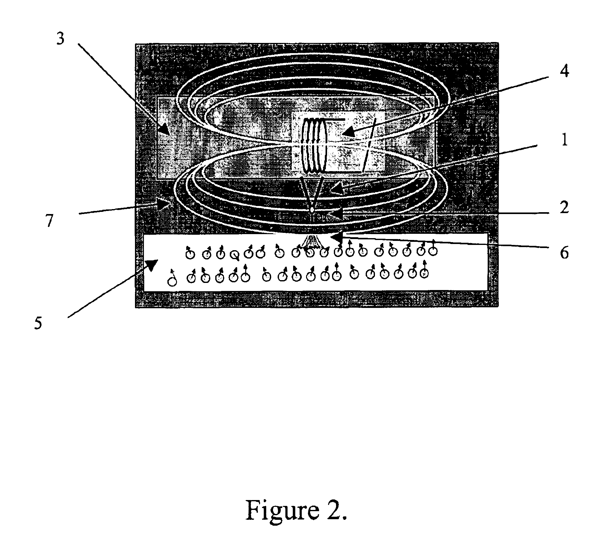
[0017]Another aspect of the present invention involves a method of detection for nanoscale MRFM using a carbon nanotube cantilever. Readout of the cantilever can be achieved electrically, eliminating the need for optical interferometry or other optical detection methods, which become problematic as cantilever dimensions are reduced to sub-optical-wavelength. The method uses the intrinsic piezoelectric or piezoresistance properties of the carbon nanotubes to provide a readout in the nanoscale MRFM device.

Problems solved by technology

As the cantilever size decreases, optical detection becomes increasingly difficult, especially when the cantilever dimensions approach or become less than the wavelength of the light in the detector beam.
Micro-dimensional probes that are capable of detecting single proton and single electron spin are therefore, not possible using present cantilevers.

Method used


Image

  • Nanotube cantilever probes for nanoscale magnetic microscopy
  • Nanotube cantilever probes for nanoscale magnetic microscopy
  • Nanotube cantilever probes for nanoscale magnetic microscopy

Examples


example 1

Preparation of Catalyst Substrate for Synthesis of Linear CNTs

[0059]Mesoporous silica containing iron nanoparticles were prepared by a sol-gel process by hydrolysis of tetraethoxysilane (TEOS) in the presence of iron nitrate in aqueous solution following the method described by Li et al. (Science, (1996), Vol. 274,1701 -3) with the following modification. The catalyst gel was dried to remove excess water and solvents and calcined for 10 hours at 450° C. and 10−2 torr to give a silica network with substantially uniform pores containing iron oxide nanoparticles that are distributed within. The catalyst gel is then ground into a fine, micro-particulate powder either mechanically using a ball mill or manually with a pestle and mortar. The ground catalyst particles provide particle sizes that range between 0.1 and 100 μM under the grinding conditions.

example 2

Preparation of Catalyst Substrate for Synthesis of Branched CNTs

[0060]Catalyst substrates were prepared following the method described by Li et al. (Applied Physics Letters (2001) Vol. 79(12), 1879-1881). Magnesium oxide (MgO) supported cobalt (Co) catalysts were prepared by dissolving 0.246 g of cobalt nitrate hexahydrate (Co(NO3)2.6H2O, 98%) in 40 ml ethyl alcohol, following immersing 2 g of particulate MgO powder (−325 mesh) were added to the solution with sonication for 50 minutes. The solid residue was filtered, dried and calcined at 130° C. for 14 hours.

example 3

General Synthetic Procedure for Branched CNTs

[0061]The MgO supported cobalt catalyst of Example 2 were first reduced at 1000° C. for 1 hour in a pyrolytic chamber under a flow of a mixture hydrogen (40 sccm) and nitrogen (100 sccm) at a pressure of 200 Torr. The nitrogen gas was subsequently replaced with methane (10 sccm) to initiate CNT growth. The optimum reaction time for producing branched CNTs was 1 hour.


PUM


Abstract

The present invention provides an MFM or MRFM analytical device comprising a micro-dimensional probe that is capable of detecting single proton and single electron spin. Furthermore, it provides an MFM or MRFM device comprising a micro-dimensional probe, that is capable of detecting magnetic structures of size of order one nanometer. In particular, the present invention provides a micro-dimensional probe for an MFM or MRFM device that comprises a CNT cantilever that comprises a nanoscale ferromagnetic material. The CNT cantilever can be attached to an electrode as a component of a microscopic probe which is coupled with an electrical circuit as a component of a device for nanoscale MFM or MRFM micro-dimensional probes. The device comprising the probe and electrical circuit can be incorporated into an existing scanning probe microscope (SPM) apparatus having accommodation for electrical readout.

Description

RELATED APPLICATION[0001]This application claims the benefit of U.S. Provisional Application No. 60 / 412,319, filed on Sep. 20, 2002. The entire teachings of the above application are incorporated herein by reference.GOVERNMENT SUPPORT[0002]The present invention was made with partial support from The National Science Foundation Grant Number 0210533. The United States Government retains certain rights to the invention.FIELD OF THE INVENTION[0003]The present invention relates to micro-dimensional analytical probes for Magnetic Force Microscopy and Magnetic Resonance Force Microscopy. In particular, the present invention relates to nanoscale materials having piezoelectric properties such as carbon nanotubes (CNTs) with pre-determined morphology that function as electromagnetic analytical probes in a Magnetic Force Microscopy or Magnetic Resonance Force Microscopy deviceBACKGROUND OF THE INVENTION[0004]Magnetic Force Microscopy (hereinafter referred to as MFM) and Magnetic Resonance Forc...

Claims


Application Information

Patent Timeline
IPC IPC(8): G01R33/038G12B21/10G12B21/00G01Q60/50G01Q60/52G01Q70/12
CPCB82Y15/00G01R33/0385G01Q60/52G01Q70/12B82Y35/00B82Y25/00
Inventor NAUGHTON, MICHAEL J.
Owner BOSTON COLLEGE
Learn More