Temporary Vascular Scaffold and Scoring Device

a technology of which is applied in the field of temporary vascular scaffold and scoring device, can solve the problems of high cost, fatality, and ineffective peripheral circulation of des, and achieve the effects of preventing complications, good patient outcomes, and cost-effectiveness

Active Publication Date: 2014-05-22
NFINIUM VASCULAR TECH
View PDF11 Cites 54 Cited by
  • Summary
  • Abstract
  • Description
  • Claims
  • Application Information

AI Technical Summary

Benefits of technology

[0021]To address the problem of how best to deliver the drugs in the most cost effective manner available while producing good patient outcomes and preventing complications, the medical device industry has essentially focused on developing methods and devices that inhibit the vascular response to the injury (restenosis), as opposed to developing a device that causes less injury, and hence less restenosis. One aspect of the present invention is directed to a device and method that both causes less injury to the vasculature by the use of dilatation of a specialized braid over a balloon causing less dissection and more even plaque disruption at lower pressures and intro

Problems solved by technology

However, DES are extremely expensive and can lead to thrombosis, which can prove fatal.
In addition, DES are not particularly effective in the peripheral circulation.
The expense of drug eluting stents at over $3000 each dramatically increases the overall cost of healthcare in the U.S. Finally, not only are the stents are costly, but expensive and potentially harmful drugs are routinely used for at least a year after stent implantation.
Because of variable plaque morphology and composition, stresses provided by conventional POBA can be unpredictable, and frequently high pressure balloon inflations are often needed to successfully provide enough stress to crack the plaque.
When the plaque does compress at high pressures, the balloon will often very rapidly expand to its full dimension in a noticeable pop (tenths of a second), very rapidly expanding the vessel wall often rupturing the smooth muscle cells.
Dissection frequently occurs, as does irreparable injury to t

Method used


Image

  • Temporary Vascular Scaffold and Scoring Device
  • Temporary Vascular Scaffold and Scoring Device
  • Temporary Vascular Scaffold and Scoring Device

Examples


Embodiment Construction

[0068]The following description will typically be with reference to specific structural embodiments and methods. It is to be understood that there is no intention to limit the invention to the specifically disclosed embodiments and methods but that the invention may be practiced using other features, elements, methods and embodiments. Preferred embodiments are described to illustrate the present invention, not to limit its scope, which is defined by the claims. Those of ordinary skill in the art will recognize a variety of equivalent variations on the description that follows. Like elements in various embodiments are commonly referred to with like reference numerals.

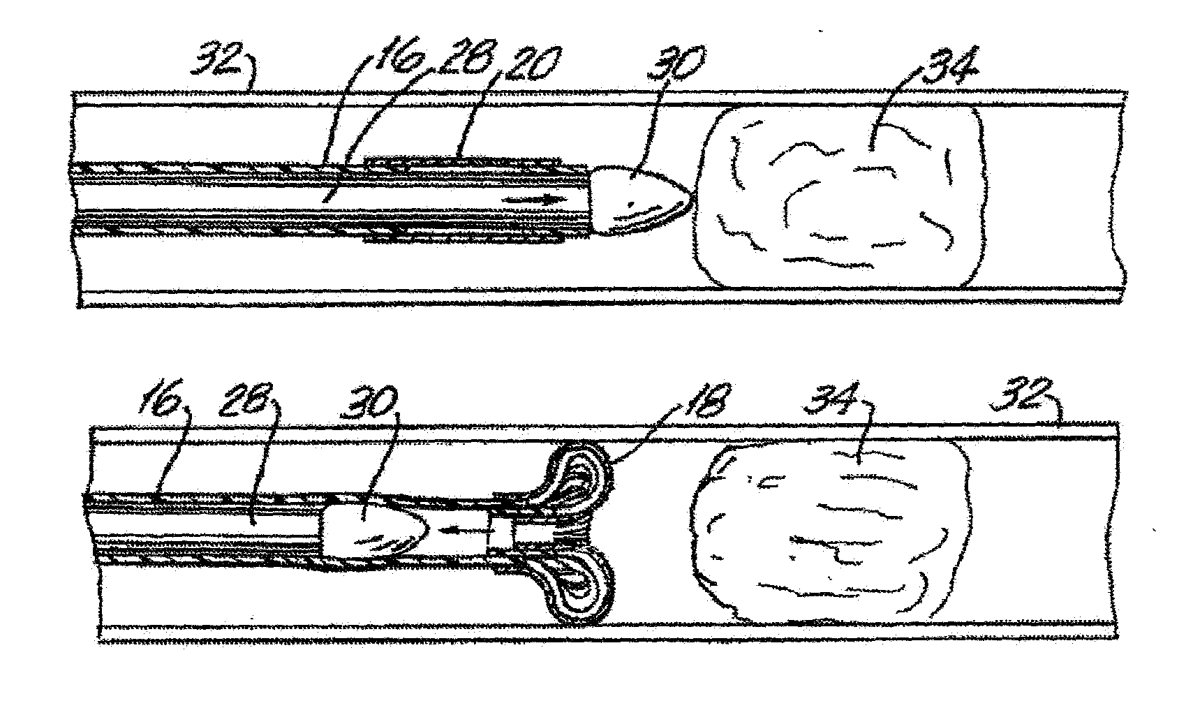
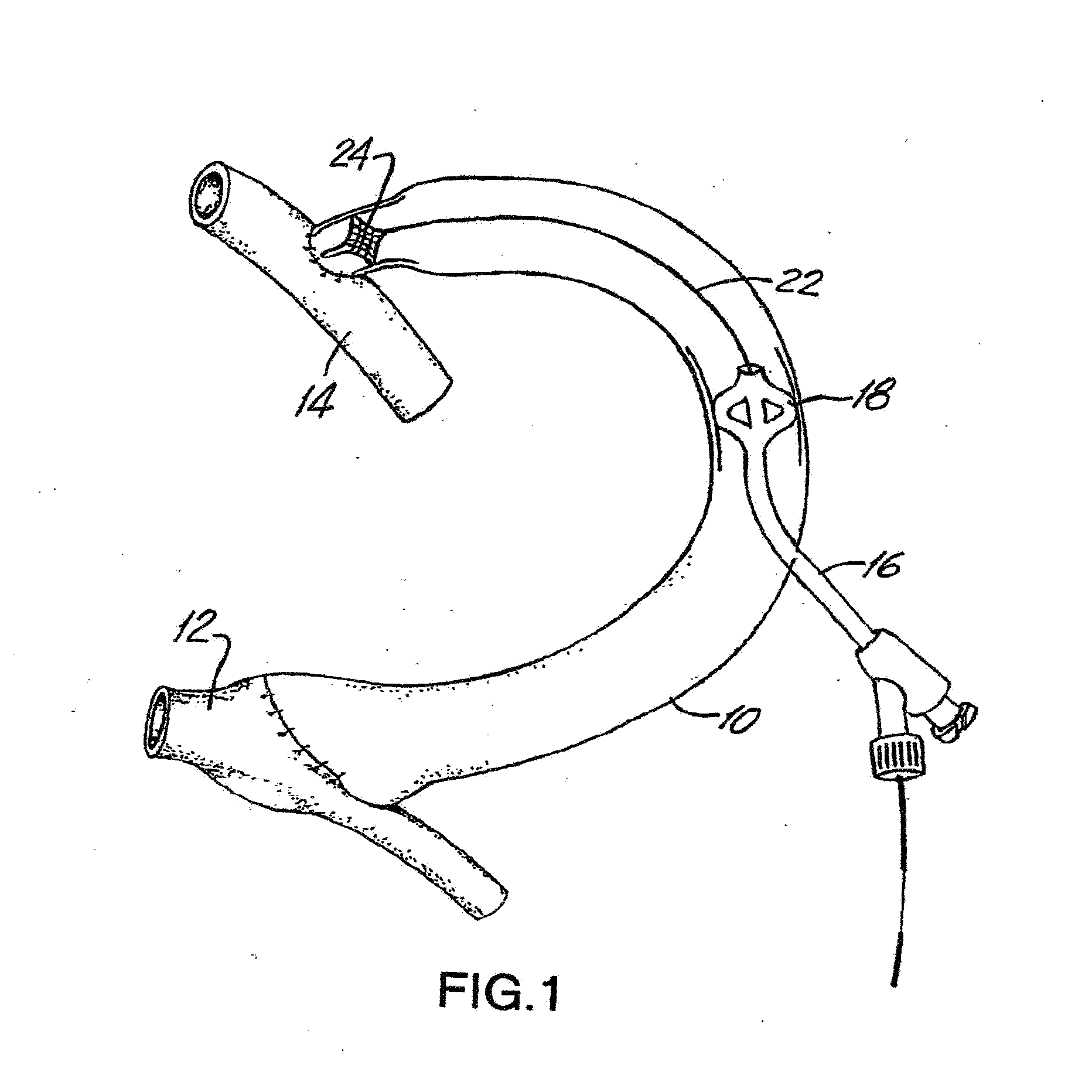
[0069]FIG. 1 shows a typical synthetic graft 10 used in hemodialysis. The graft extends between a vein 12 and an artery 14. The graft 10 may be about thirty centimeters long with an inner diameter (I.D.) of 6 or 7 millimeters. A catheter 16 can be inserted through the wall of the graft or vessel. Typically, the catheter ...


PUM


Abstract

Devices and methods for treating a target site in a body lumen are provided. A medical device includes a stent-like structure including a plurality of scoring and non-scoring filaments interwoven with one another. Generally, the stent-like structure will have more non-scoring filaments than scoring filaments to provide greater structural support and to focus the scoring forces on only a few select areas. The stent-like structure is expanded within the target site to score the target site and to provide temporary structural support while the target site is infused with a therapeutic agent. Such therapeutic agent infusion occurs with the use of a drug eluting or drug coated balloon disposed within the stent-like structure or by occluding the target site and introducing a drug into the occluded target site to sit for a period of time.

Description

CROSS-REFERENCE TO OTHER APPLICATIONS[0001]This application claims the benefit of U.S. Provisional Application No. 61 / 796,596, filed Nov. 15, 2012, which application is incorporated herein by reference.[0002]This application is related to co-pending and co-owned U.S. patent application Ser. No. 12 / 813,339 filed on Jun. 10, 2010, which claims the benefit of U.S. Provisional Application No. 61 / 274,165 filed on Aug. 13, 2009 and U.S. provisional application No. 61 / 277,154 filed on Sep. 21, 2009, the disclosures of which are incorporated by reference.[0003]This application is also related to co-owned U.S. Pat. No. 6,238,412, the disclosure of which is incorporated by reference.BACKGROUND OF THE INVENTION[0004]Balloon angioplasty has been a popular method of treating vascular occlusions since 1976. With plain old balloon angioplasty (POBA), there exists a significant subset of patients who have immediate suboptimal results related to the trauma to the vessel including dissection of the v...

Claims


Application Information

Patent Timeline
IPC IPC(8): A61B17/3207
CPCA61B17/320725A61B17/221A61B2017/22061A61B2017/22084A61M25/104A61B2017/32096A61M2025/105A61F2/82
Inventor FULTON, III, RICHARD EUSTIS
Owner NFINIUM VASCULAR TECH
Why Eureka
Try Eureka