
Settling Time and Effective Band Width for Op-Amps Using Miller Capacitance Compensation

a technology of miller capacitance compensation and effective band width, which is applied in the direction of electric variable regulation, process and machine control, instruments, etc., can solve the problems of limiting the circuit's dynamic performance, power supply dropout can be an issue, and the existence of two closed feedback loops for the op-amp

Inactive Publication Date: 2014-06-12
SANDISK TECH LLC
View PDF4 Cites 24 Cited by
  • Summary
  • Abstract
  • Description
  • Claims
  • Application Information

AI Technical Summary

Benefits of technology

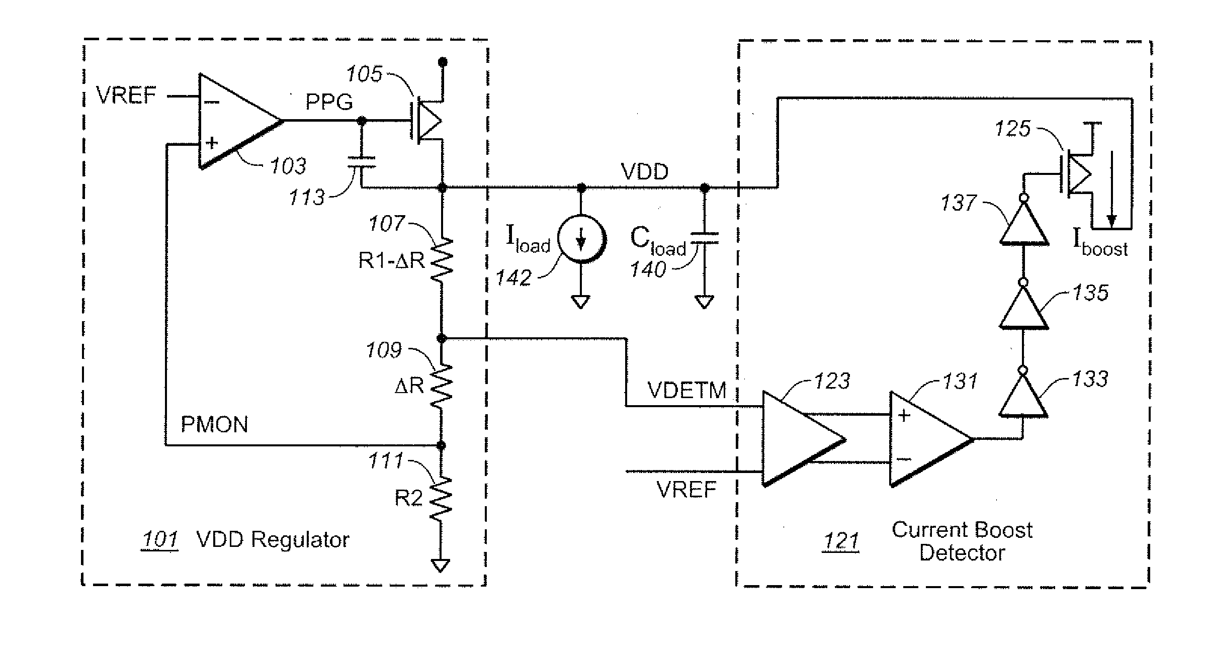
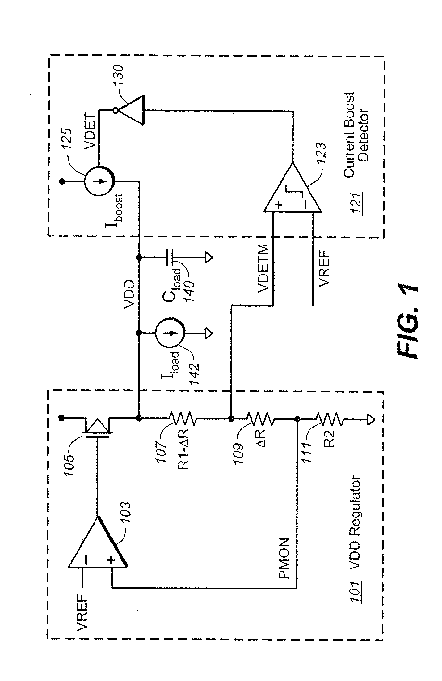
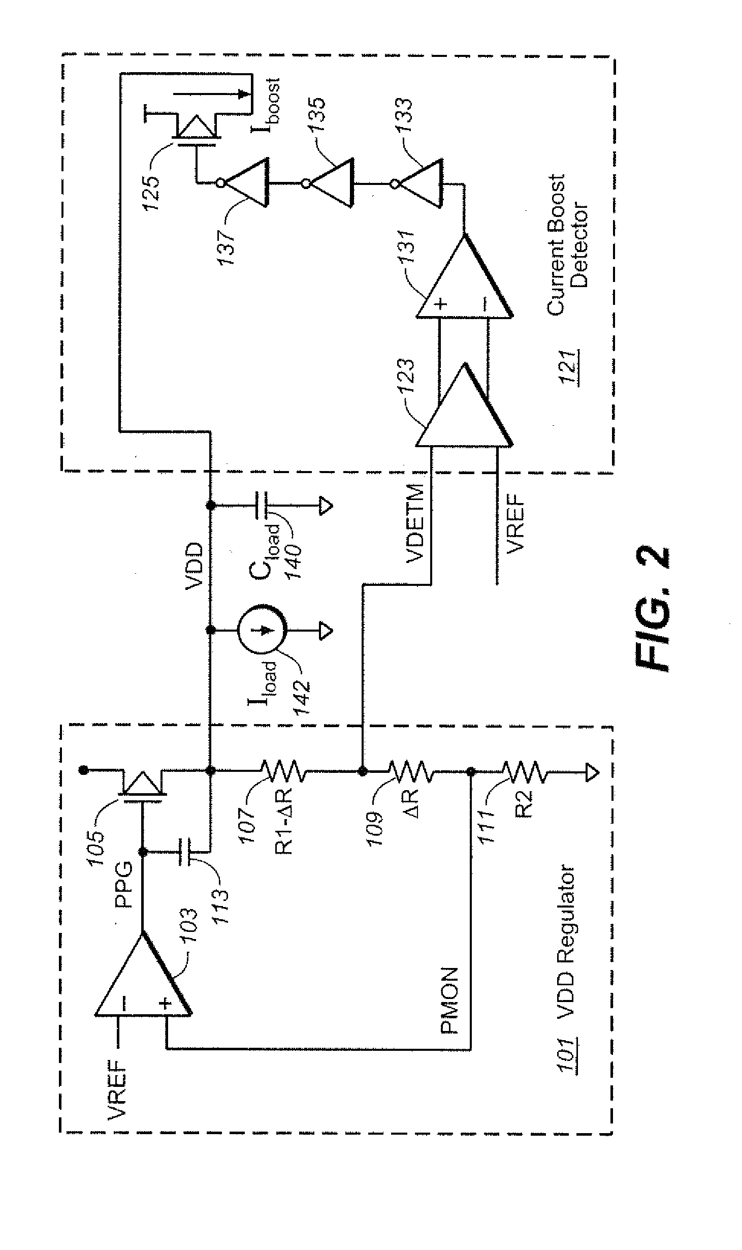
The invention presents a voltage regulator circuit that includes a power transistor, an error amplifier, a voltage divider circuit, a current source circuit, a comparator, and a supplementary current source section. The voltage regulator circuit can supply a load on an integrated circuit. The technical effects of the invention include improved accuracy and stability of voltage regulation, as well as reduced power consumption and improved efficiency.

Problems solved by technology

In low drop-out regulator designs, power supply drop-out can be an issue due to higher frequency switching, load dump and higher power consumption.
Two of the issues that can arise from high frequency operations are start-up settling time specification and steady state supply load dump recovery specification.
One of the drawbacks of using Miller capacitance compensation is the existence of two closed feedback loops for the Op-amp.
However, if output of the op-amp is significantly disturbed, such as is the case when connecting to a load or when the load has fast switching characteristics, then a second closed loop formed from the output through the miller capacitance directly to the output of error amplifier and then on to the output of the op-amp.
This type of compensation scheme limits the circuit's dynamic performance due to its slew rate in initial settling time and steady state load dump recovery speed.

Method used


Image

  • Settling Time and Effective Band Width for Op-Amps Using Miller Capacitance Compensation
  • Settling Time and Effective Band Width for Op-Amps Using Miller Capacitance Compensation
  • Settling Time and Effective Band Width for Op-Amps Using Miller Capacitance Compensation

Examples


Embodiment Construction

[0014]The following looks at techniques for helping with the problems discussed in the Background by introducing a comparator and a current source. First a pair of embodiments for case of an LDO / HDO are considered, starting with an example using supplementary current source for low output voltage detection followed by looking at far-side regulated supply drop-off detection and current boosting. After these, a section looks at operational amplifiers using Miller capacitance compensation.

LDO: Current Boost by Low Voltage Detection

[0015]This section considers drop-out at the voltage regulator and the next addresses drop-out far away from the regulator. Supply drop-out can occur during start-up due to the fact that the regulator is slewing its compensation capacitance before reaching steady state. Steady state drop-out recovery can occur during high load dump operation, as the regulator bandwidth is typically smaller than the inverse of the time constant of the load dump operations; the...


PUM


Abstract

An LDO / HDO circuit adds a supplementary current source to supply the output node. The current boosting section includes a digital comparator with a first input connected to the LDO's feedback loop and a second input connected to a reference level. The comparator then generates a digital output used to control the supplementary current source. This approach also can be used in a far-side implementation, where the local supply level for the load is boosted by the current source based a comparison of this local level and the output of the LDO. Miller capacitive compensation is also considered. Current in shunted to ground from a node in the Miller loop, where the level is controlled by the output of a digital comparator base on a comparison of the circuit's output voltage and a reference level.

Description

FIELD OF THE INVENTION[0001]This application claims priority to and the benefit of U.S. Provisional Application No. 61 / 734,880, filed Dec. 7, 2012, and is related to U.S. patent application Ser. No. ______ filed ______, 2013, entitled “A LDO / HDO Architecture Using Supplementary Current Source to Improve Effective System Bandwidth,” which applications are incorporated herein in their entirety by this reference.BACKGROUND[0002]Voltage regulation circuits have many applications in power supply systems to provide a regulated voltage at a predetermined multiple of a reference voltage. In low drop-out regulator designs, power supply drop-out can be an issue due to higher frequency switching, load dump and higher power consumption. Two of the issues that can arise from high frequency operations are start-up settling time specification and steady state supply load dump recovery specification. There is consequently room for improvement in the design of low drop out regulation circuits.[0003]...

Claims


Application Information

Patent Timeline
Patent Type & Authority Applications(United States)
IPC IPC(8): G05F1/10
CPCG05F1/575G05F1/10
Inventor PAN, FENGWANG, SUNG-ENYIN, JIANG
Owner SANDISK TECH LLC
Learn More