
Diffractive optical element and manufacturing method for the same

a technology of diffractive optical elements and manufacturing methods, applied in the direction of optical elements, lenses, instruments, etc., can solve the problems of deterioration of image quality, reduced light shielding ability as a film, and partial removal of light shielding layer that must remain on the grating wall surface, so as to achieve high light shielding ability and without deterioration of optical characteristics.

Active Publication Date: 2014-06-12
CANON KK
View PDF8 Cites 1 Cited by
  • Summary
  • Abstract
  • Description
  • Claims
  • Application Information

AI Technical Summary

Benefits of technology

[0011]It is an object of the present invention to provide a diffractive optical element and a manufacturing method for the same, which enable forming a light shielding layer having high light shielding ability on a grating wall surface without deteriorating optical characteristics of an optical effective surface of the diffractive optical element.

Problems solved by technology

If there is a lot of flare, image quality is largely deteriorated.
According to the above-mentioned conventional technologies, it is possible to form the light shielding layer on the grating wall surface, but there are problems as follows.
Further, when the lift-off process is performed, there occurs a problem that the light shielding layer that must remain on the grating wall surface is partially removed.
If the density of the light shielding film is low, light shielding ability as a film is decreased, and hence a sufficient effect for the flare suppression cannot be obtained.
Further, there is another problem in that a region where the light shielding layer is not formed occurs on the grating wall surface.
If the region where the light shielding layer is not formed occurs on the grating wall surface, the flare suppression is not performed on the region, and hence a sufficient effect for the flare suppression cannot be obtained as a whole.
However, because the film having uniform density and thickness is formed on the entire surface, a contrast of etching rate between the flat portion and the grating wall surface cannot be obtained sufficiently.
As a result, when etching the flat portion, the grating wall surface is also etched and the film of the grating wall surface becomes a low density film, and hence a desired function of the film cannot be obtained sufficiently.
As a specific problem in a case of a diffraction grating, light shielding performance is insufficient so that a sufficient effect for the flare suppression cannot be obtained.
On the contrary, if the etching is stopped in the state in which sufficient light shielding performance can be obtained in the film of the grating wall surface, the film remains also on the optical effective surface, and hence a problem such as a decrease in transmittance occurs.
Therefore, there is also a problem in that when the inorganic material is etched, etching rate contrast cannot be secured compared with the case of the organic material.

Method used


Image

  • Diffractive optical element and manufacturing method for the same
  • Diffractive optical element and manufacturing method for the same
  • Diffractive optical element and manufacturing method for the same

Examples


example 1

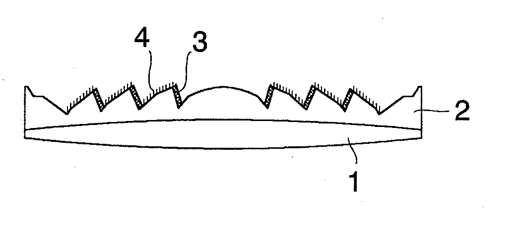
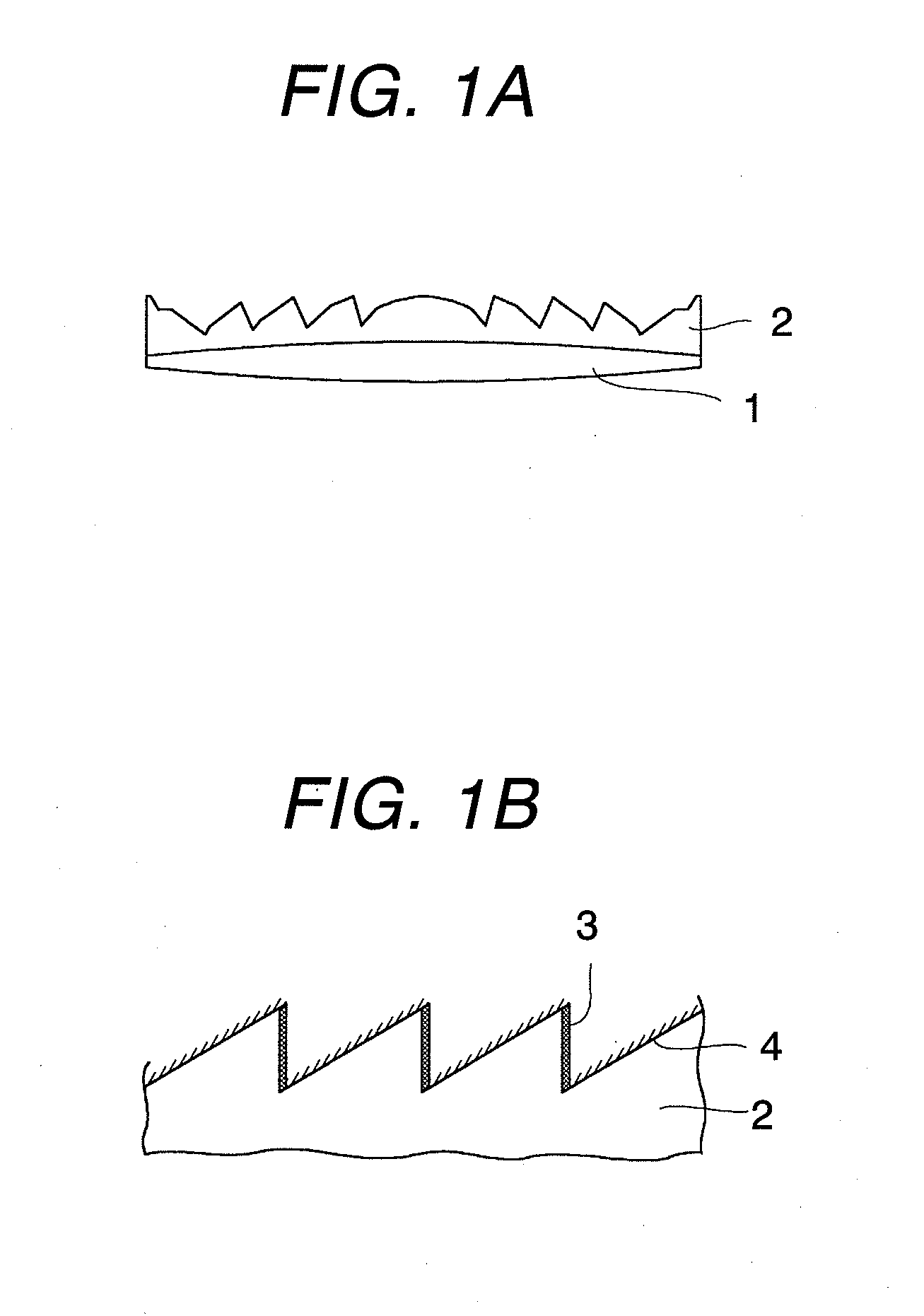
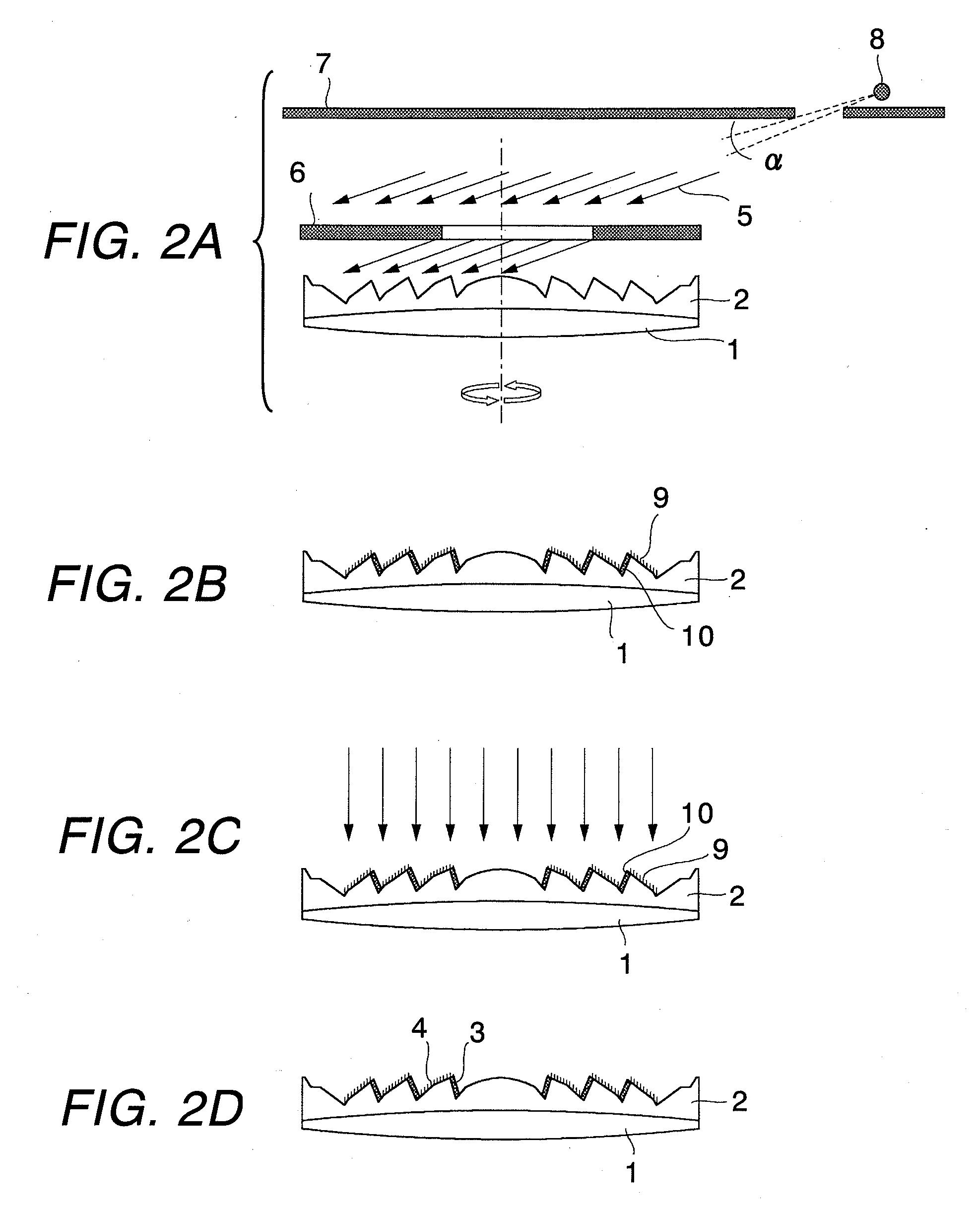
[0029]As illustrated in FIG. 1A, on the base substrate 1, the diffraction grating 2 having a desired shape using an ultraviolet curing resin was formed by replica molding so that a diffractive optical element was obtained.

[0030]The base substrate 1 was a lens of optical glass (S-BSL7, manufactured by OHARA INC.) having a radius of 58 mm and a thickness of 10.9 mm and containing boron and silicon. The ultraviolet curing resin used was a material whose main components were urethane modified polyester acrylate and dicyclopentenyloxyethyl methacrylate and in which ITO fine particles were dispersed. The grating height of the diffraction grating 2 was 10 μm, and the interval between adjacent gratings was 0.1 mm to 3.8 mm. The interval between gratings became narrower from the inside of the base substrate toward the outside.

[0031]Before forming the Al layer, oxygen plasma asking was performed on the obtained diffractive optical element at atmospheric pressure, and the diffractive optical e...


PUM

PropertyMeasurementUnit
thicknessaaaaaaaaaa
thicknessaaaaaaaaaa
densityaaaaaaaaaa

Abstract

An Al film is formed so that film forming particles are incident at normal incidence to grating wall surfaces of a diffraction grating having multiple grating portions and are incident at oblique incidence to optical effective surfaces. After that, oxidation treatment is performed from a direction to be incident at normal incidence to the optical effective surface so that the Al layer on the optical effective surface is changed to Al2O3 layer. Hence, in the diffraction grating having the multiple grating portions, the Al2O3 layer is formed on the optical effective surface for transmitting light, and the Al layer is formed on the grating wall surfaces as a light shielding layer. Thus, flare of the diffractive optical element can be suppressed.

Description

BACKGROUND OF THE INVENTION[0001]1. Field of the Invention[0002]The present invention relates to a diffractive optical element to be used for an optical apparatus such as a camera or a video camera, and a manufacturing method for the same.[0003]2. Description of the Related Art[0004]A diffractive optical element typified by a diffraction grating includes multiple grating portions arranged in a concentric manner, and each of the grating portions has an optical effective surface for forming an image of incident light at a desired position and a grating wall surface that does not work as an optical element. If light from outside of an effective screen enters the grating wall surface, the light may reach a position shifted from a desired position of image formation and become flare. If there is a lot of flare, image quality is largely deteriorated. In order to suppress the flare, it is effective to form a light shielding layer on the grating wall surface, and there are proposed various ...

Claims


Application Information

Patent Timeline
Patent Type & Authority Applications(United States)
IPC IPC(8): G02B5/18
CPCG02B5/18G02B5/1876C23C14/042C23C14/20C23C14/225C23C14/24C23C14/5853G02B3/08G02B5/1814G02B5/1842G02B5/1895G02B5/22
Inventor IWATA, KENICHI
Owner CANON KK
Learn More