Unlock instant, AI-driven research and patent intelligence for your innovation.
Substrate processing apparatus and substrate processing method
Active Publication Date: 2014-06-12
SCREEN SEMICON SOLUTIONS CO LTD
View PDF2 Cites 9 Cited by
Summary
Abstract
Description
Claims
Application Information
AI Technical Summary
This helps you quickly interpret patents by identifying the three key elements:
Problems solved by technology
Method used
Benefits of technology
Benefits of technology
The present invention provides a substrate processing apparatus and method that improves throughput. The use of a sub-transport mechanism reduces the number of transportation steps and the burden on the main transport mechanism, resulting in improved throughput.
Problems solved by technology
However, when processing different and independent from each other is performed in the first and second processing blocks using this substrate processing apparatus, throughput of the second processing block is restricted by throughput of the first processing block.
Method used
Image
Click on the blue label to locate the original text in one second.
Reading with bidirectional positioning of images and text.
Examples
first embodiment
[1] First Embodiment
(1) Configuration of Substrate Processing Apparatus
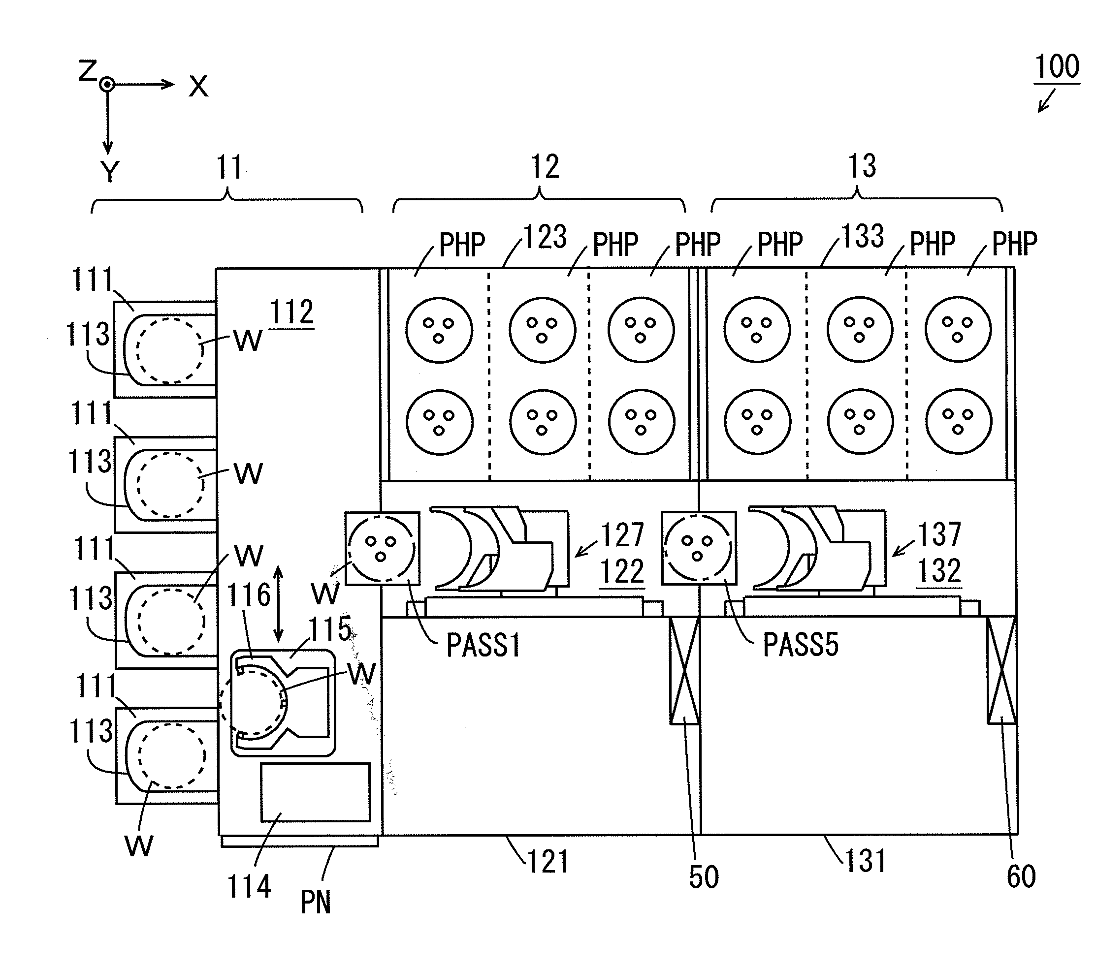
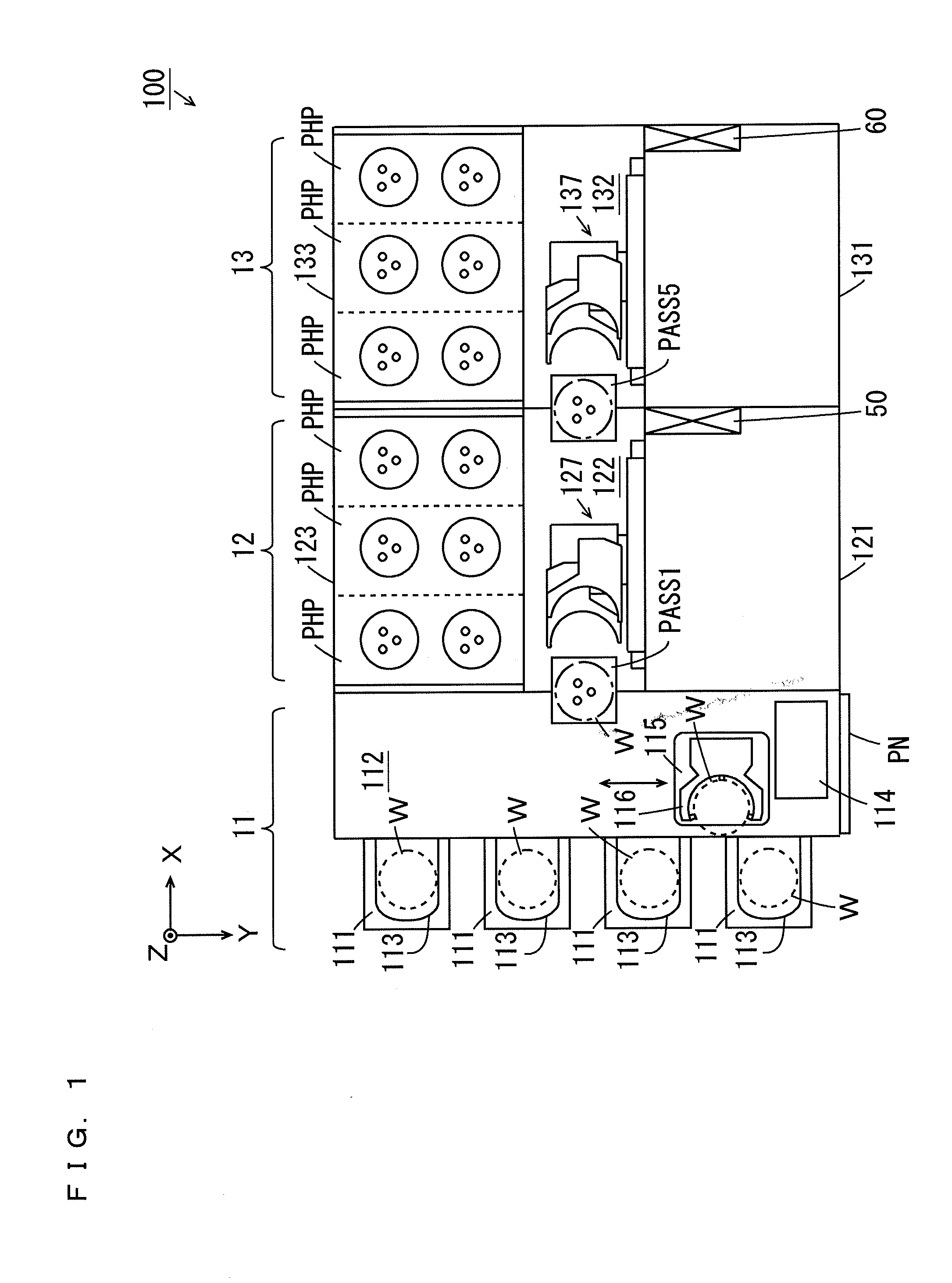
[0068]FIG. 1 is a schematic plan view of the substrate processing apparatus according to the first embodiment of the present invention. FIG. 1 and subsequent given diagrams are accompanied by the arrows that indicate X, Y, and Z directions orthogonal to one another for the clarity of a positional relationship. The X and Y directions are orthogonal to each other within a horizontal plane, and the Z direction corresponds to a vertical direction. Note that the direction toward the arrow is defined as +direction, and the opposite direction thereto is defined as −direction.
[0069]As shown in FIG. 1, the substrate processing apparatus 100 includes an indexer block 11 and processing blocks 12, 13. The indexer block 11 includes a plurality of carrier platforms 111 and a transport section 112. A carrier 113 that stores a plurality of substrates W in multiple stages is placed in each carrier platform 111. While a FOUP (Fron...
second embodiment
[2] Second Embodiment
(1) Configuration of Substrate Processing Apparatus
[0162]As for the substrate processing apparatus according to the second embodiment, difference from the substrate processing apparatus 100 according to the first embodiment will be described. FIG. 9 is a schematic plan view of the substrate processing apparatus according to the second embodiment of the present invention. FIG. 10 is a horizontal cross sectional view of the substrate processing apparatus 100 according to the second embodiment. In the present embodiment, the configuration of the processing block 13 is similar to the configuration of the processing block 13 in the first embodiment except for that the second processing section 131 is a development processing section.
[0163]As shown in FIGS. 9 and 10, the substrate processing apparatus 100 further includes a cleaning / drying processing block 14A and a carry-in / carry-out block 14B. An interface block 14 is constituted by the cleaning / drying processing bl...
third embodiment
[3] Third Embodiment
(1) Configuration of Substrate Processing Apparatus
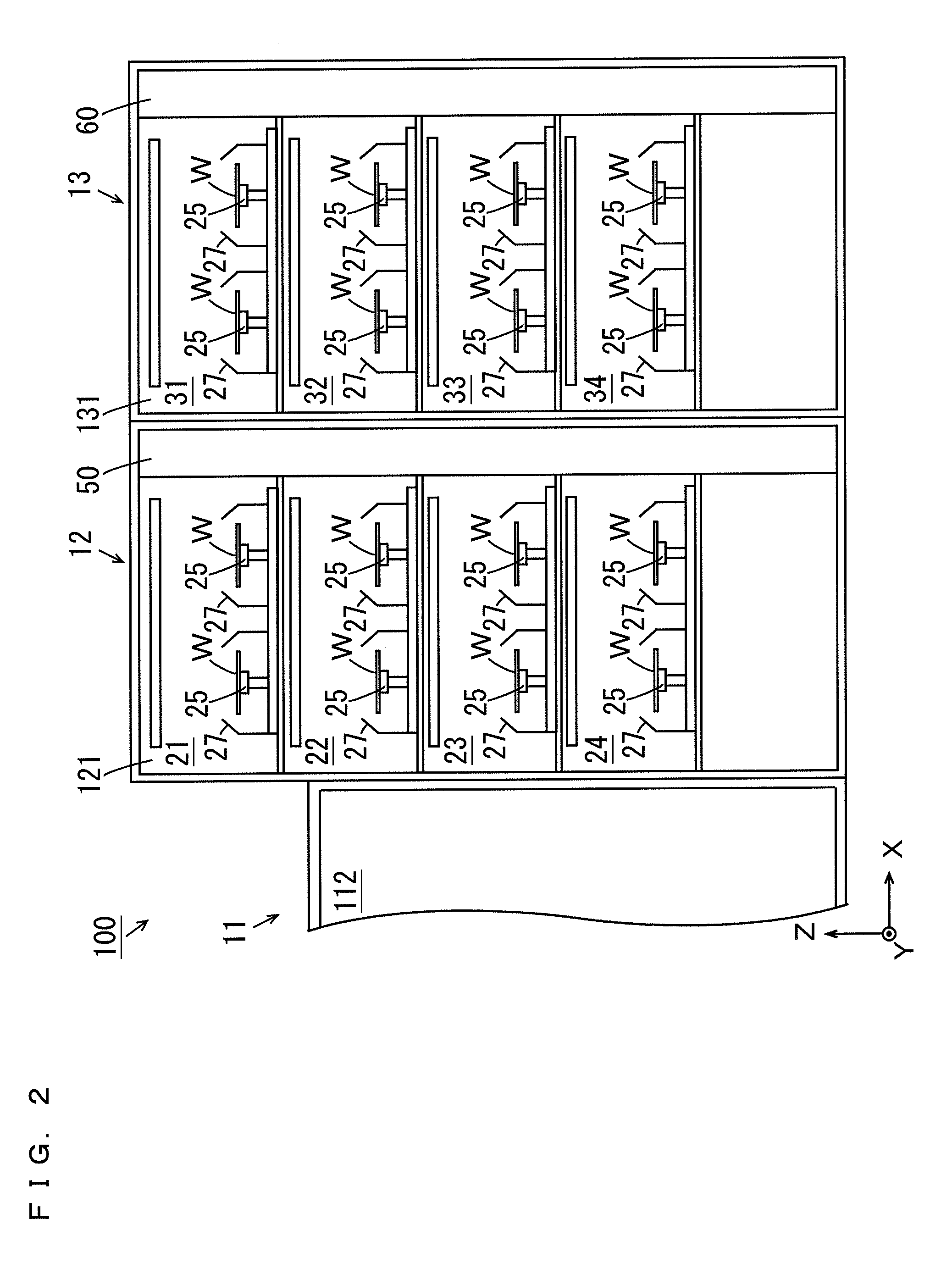
[0218]As for the substrate processing apparatus according to the third embodiment, difference from the substrate processing apparatus 100 according to the second embodiment will be described. FIG. 15 is a horizontal cross sectional view of the substrate processing apparatus 100 according to the third embodiment. FIG. 16 is a diagram of the first processing section 121, the second processing section 131 and the cleaning / drying processing section 161 of FIG. 15 as viewed in the −Y direction. FIG. 17 is a diagram of the thermal processing sections 123, 133 and the cleaning / drying processing section 162 of FIG. 15 as viewed in the +Y direction. In the present embodiment, the processing chambers 21 to 24, 32, 34 are the coating processing chambers, and the processing chambers 31, 33 are the development processing chambers.
[0219]As shown in FIG. 16, the plurality of spin chucks 25, the plurality of cups 27 and the plur...
PUM
Abstract
One processing block is arranged between an indexer block and another processing block. One substrate is transported to a main transport mechanism in the one processing block by a main transport mechanism in the indexer block, transported to a first processing section and a thermal processing section by the main transport mechanism in the one processing block and processing is performed on the substrate. The substrate after the processing is transported to the main transport mechanism in the indexer block by the main transport mechanism in the one processing block. Another substrate is transported to a sub-transport mechanism in a sub-transport chamber by the main transport mechanism in the indexer block, and is transported to a main transport mechanism in another processing block by the sub-transport mechanism in the sub-transport chamber. The substrate is transported to the sub-transport mechanism in the sub-transport chamber by the main transport mechanism in another processing block, and is transported to the main transport mechanism in the indexer block by the sub-transport mechanism in the sub-transport chamber.
Description
BACKGROUND OF THE INVENTION[0001]1. Field of the Invention[0002]The present invention relates to a substrate processing apparatus and a substrate processing method.[0003]2. Description of Related Art[0004]Substrate processing apparatuses are used to subject various types of substrates such as semiconductor substrates, substrates for liquid crystal displays, plasma displays, optical disks, magnetic disks, magneto-optical disks, and photomasks, and other substrates to various types of processing (see JP 2011-66049 A, for example).[0005]The substrate processing apparatus described in JP 2011-66049 A includes an indexer block and first and second processing blocks. The first and second processing blocks include first and second transport sections, respectively. The unprocessed substrate is transported from the indexer block to the first processing block by the first transport section. In the first processing block, first processing is performed on the substrate. Thereafter, the substrat...
Claims
Application Information
Patent Timeline
Application Date:The date an application was filed.
Publication Date:The date a patent or application was officially published.
First Publication Date:The earliest publication date of a patent with the same application number.
Issue Date:Publication date of the patent grant document.
PCT Entry Date:The Entry date of PCT National Phase.
Estimated Expiry Date:The statutory expiry date of a patent right according to the Patent Law, and it is the longest term of protection that the patent right can achieve without the termination of the patent right due to other reasons(Term extension factor has been taken into account ).
Invalid Date:Actual expiry date is based on effective date or publication date of legal transaction data of invalid patent.
