Battery monitoring apparatus

a battery monitoring and battery technology, applied in the field can solve the problems of insufficient attenuation of common mode noise (in-phase fluctuation), drastic increase of manufacturing cost of battery monitoring apparatus, and malfunction of monitoring circuit, so as to reduce the fluctuation of cutoff frequency

Active Publication Date: 2014-06-26
DENSO CORP
View PDF3 Cites 19 Cited by
  • Summary
  • Abstract
  • Description
  • Claims
  • Application Information

AI Technical Summary

Benefits of technology

[0025]Thus, the cutoff frequency of the second filter circuit is ensured to be larger than the cutoff frequency of the first filter circuit. This can minimize the fluctuation of the cutoff frequency in the first filter circuit, the fluctuation being attributed to the addition of the second filter circuit.

Problems solved by technology

However, this filter configuration is not able to sufficiently attenuate common mode noise (in-phase fluctuation) generated between the individual connecting lines and a ground line.
In this way, common mode noise is not sufficiently attenuated in the filter configuration disclosed in JP-A-2012-159406, and there is a probability that the common mode noise would enter the monitoring circuit, which leads to the probability of causing malfunction in the monitoring circuit.
This raises a problem of drastically increasing the cost incurred in manufacturing the battery monitoring apparatus.

Method used


Image

  • Battery monitoring apparatus
  • Battery monitoring apparatus
  • Battery monitoring apparatus

Examples


first embodiment

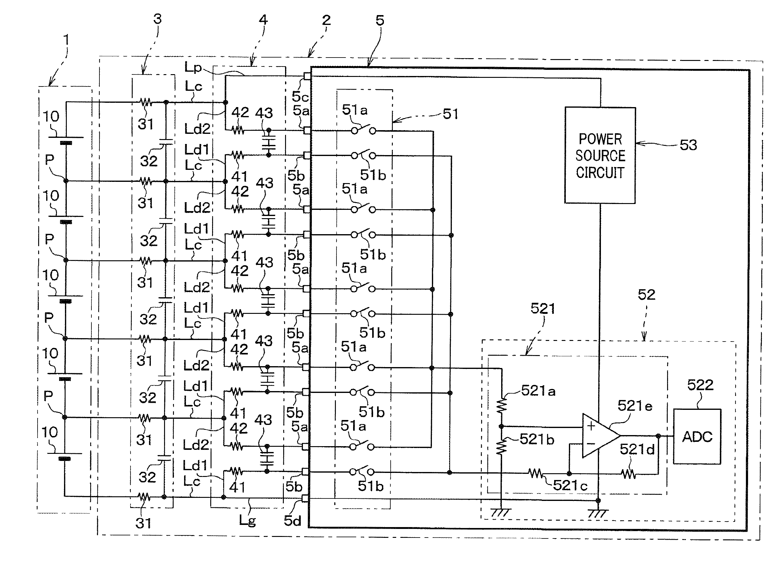
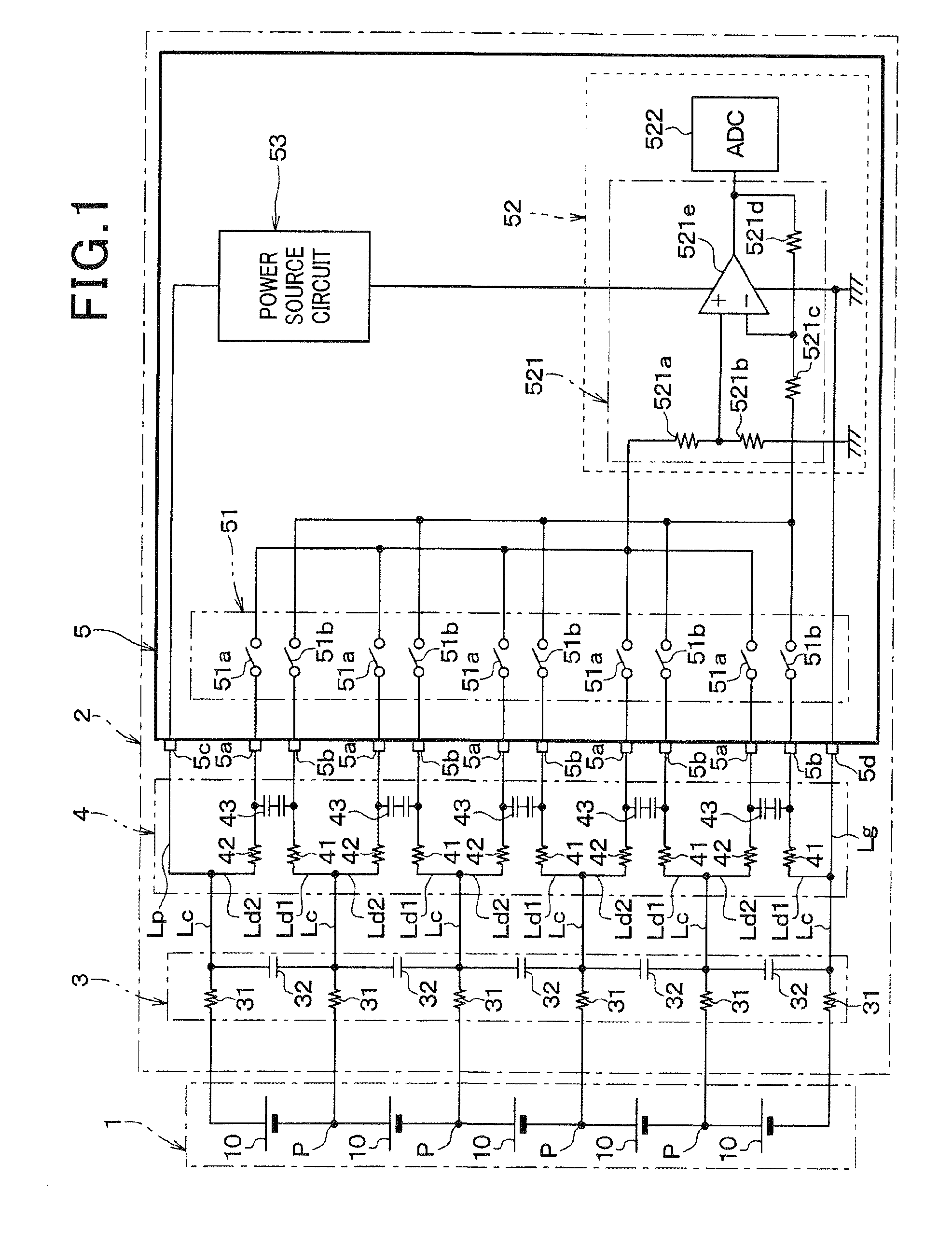
[0036]Referring to FIGS. 1 and 2, a first embodiment of the present invention is described. In the present embodiment, a battery monitoring apparatus 2 is applied to a battery pack 1 which is installed in a vehicle such as a hybrid vehicle or an electric vehicle. In this embodiment, the battery pack 1 and the battery monitoring apparatus 2 configure a battery system for vehicles.

[0037]The battery pack 1 serves as a power source that mainly supplies electric power to an electric motor, not shown, used for driving, as well as to various electrical loads installed in the vehicle. As shown in FIG. 1, the battery pack 1 is configured as a serial connection in which a plurality of battery cells 10 composed of secondary cells, such as lithium-ion cells, are connected in series. In the example shown in FIG. 1, the battery pack 1 is configured by five battery cells 10. However, the number of the battery cells 10 configuring the battery pack 1 is not limited to five.

[0038]The battery monitori...

second embodiment

[0070]Referring now to FIGS. 3 and 4, hereinafter is described a second embodiment of the present invention. The second embodiment is different from the first embodiment in the circuit configuration of the second filter circuit 3. In the present embodiment, an explanation of components identical with or similar to each other between the first embodiment are omitted or simplified.

[0071]As shown in FIG. 3, in the present embodiment, the second capacitors 32 of the second filter circuit 3 are each connected between the first and second branch lines Ld1 and Ld2 of the respective connecting lines. In this case, the second capacitors 32 of the second filter circuit 3 is connected in series with the first capacitors 43 of the second filter circuit 4, without passing through the first resistors 41 and 42.

[0072]Specifically, each of the first capacitors 43 is connected between the second branch line Ld2 and the first branch line Ld1 of a pair of common lines Lc which are connected to the pai...


PUM


Abstract

A battery monitoring apparatus a plurality of connection lines, a monitoring circuit, a first filter circuit, and a second filter circuit. The monitoring circuit is provided with a pair of sensing terminals for each pair of positive and negative electrode terminals of each of a plurality of battery cells of a battery pack. The plurality of connection lines includes a plurality of common line and first and second branch lines. The first filter circuit includes first resistors located on the first and second branch lines connected to the pair of sensing terminals, and a first capacitor located between the first and second branch lines connected to the pair of sensing terminals. The second filter circuit includes a second resistor located on the plurality of connection lines, and a second capacitor connected in series between the plurality of connection lines without passing through the first resistors and the second resistor.

Description

CROSS-REFERENCE TO RELATED APPLICATION[0001]This application is based on and claims the benefit of priority from earlier Japanese Patent Application No. 2012-282694 filed on Dec. 26, 2012, the description of which is incorporated herein by reference.BACKGROUND[0002]1. Technical Field[0003]The present invention relates to a battery monitoring apparatus that includes a monitoring circuit for monitoring individual cell voltages of a plurality of battery cells which are connected in series to form a battery pack.[0004]2. Related Art[0005]A battery monitoring apparatus in related art is proposed that includes a monitoring circuit and a low-pass filter (for example, see JP-A-2012-159406). The monitoring circuit is provided with a plurality of pairs of sensing terminals for a plurality of battery cells. The pairs of sensing terminals are associated with the plurality of battery cells of which positive and negative electrode terminals are connected to each of the sensing terminals in a pair...

Claims


Application Information

Patent Timeline
Patent Type & Authority Applications(United States)
IPC IPC(8): G01R31/36
CPCG01R31/396
Inventor MIZOGUCHI, TOMOMICHI
Owner DENSO CORP
Why Eureka
Try Eureka