Eureka AIR delivers breakthrough ideas for toughest innovation challenges, trusted by R&D personnel around the world.

Water activated instant hydrogen generator with passive control on hydrogen demand

a water-activated, instant technology, applied in the direction of hydrogen production, electrochemical generators, chemistry apparatus and processes, etc., can solve the problems of poor reliability, complex system control, and inability to meet battery technology,

Inactive Publication Date: 2014-06-26
UNITED STATES OF AMERICA THE AS REPRESENTED BY THE SEC OF THE ARMY
View PDF9 Cites 9 Cited by
  • Summary
  • Abstract
  • Description
  • Claims
  • Application Information

AI Technical Summary

Benefits of technology

The present invention relates to an apparatus for generating hydrogen gas, which includes a first chamber containing a chemical hydride and a catalyst, a second chamber fluidly coupled to the first chamber, a connector, and a third chamber containing a resilient member to control the flow of water based on the pressure of hydrogen gas. The invention also includes a wearable power unit comprising a fuel cell and a hydrogen gas generating apparatus. The technical effects of the invention include a more efficient and controllable way for generating hydrogen gas, which can be used in wearable power units for energy storage and generation.

Problems solved by technology

Fuel cell technologies have frequently been used to fulfill the high energy density requirements which current battery technologies are unable to meet.
However, the DMFC is ill-suited as a wearable power source because it suffers from several problems, such as requiring an active battery for start-up, poor reliability and complicated system control, and low fuel to electric energy conversion efficiency.
One of the biggest challenges for a PEMFC for wearable power applications is a suitable travel-convenient hydrogen source.
In addition, such a system presents a safety risk to the user due to the close proximity of compressed gas.
However, this process requires a hot heat source (e.g. greater than 125 degrees Celsius) which can only be supplied using valuable electric power with careful control.

Method used


Image

  • Water activated instant hydrogen generator with passive control on hydrogen demand
  • Water activated instant hydrogen generator with passive control on hydrogen demand
  • Water activated instant hydrogen generator with passive control on hydrogen demand

Examples


Embodiment Construction

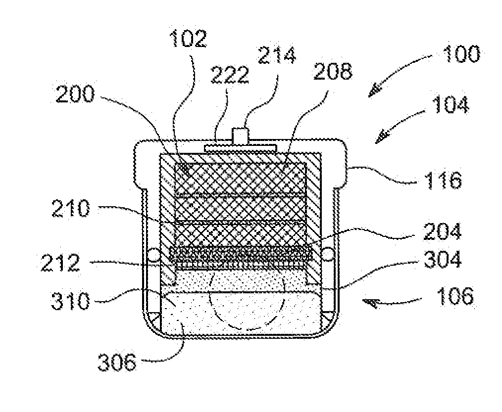
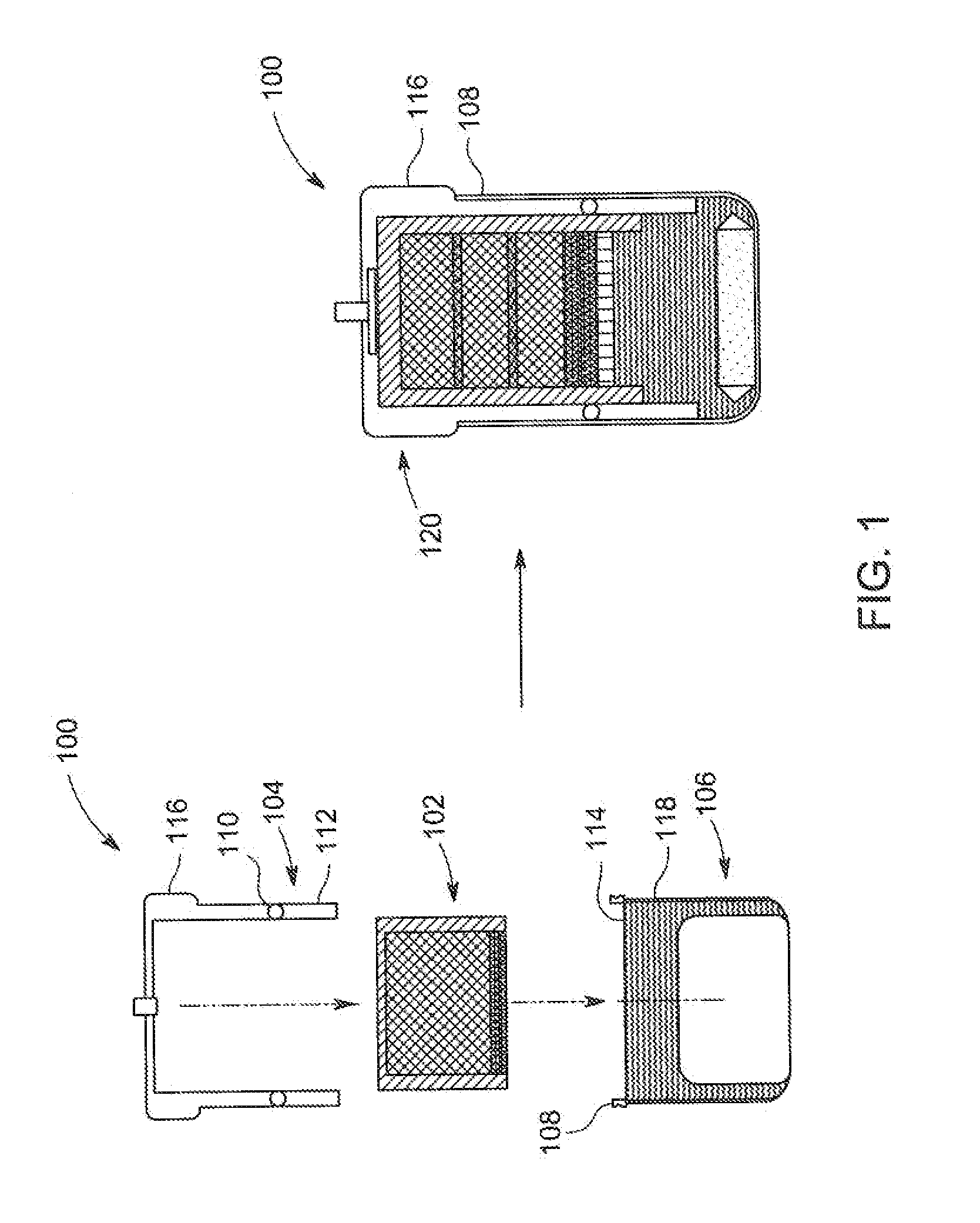
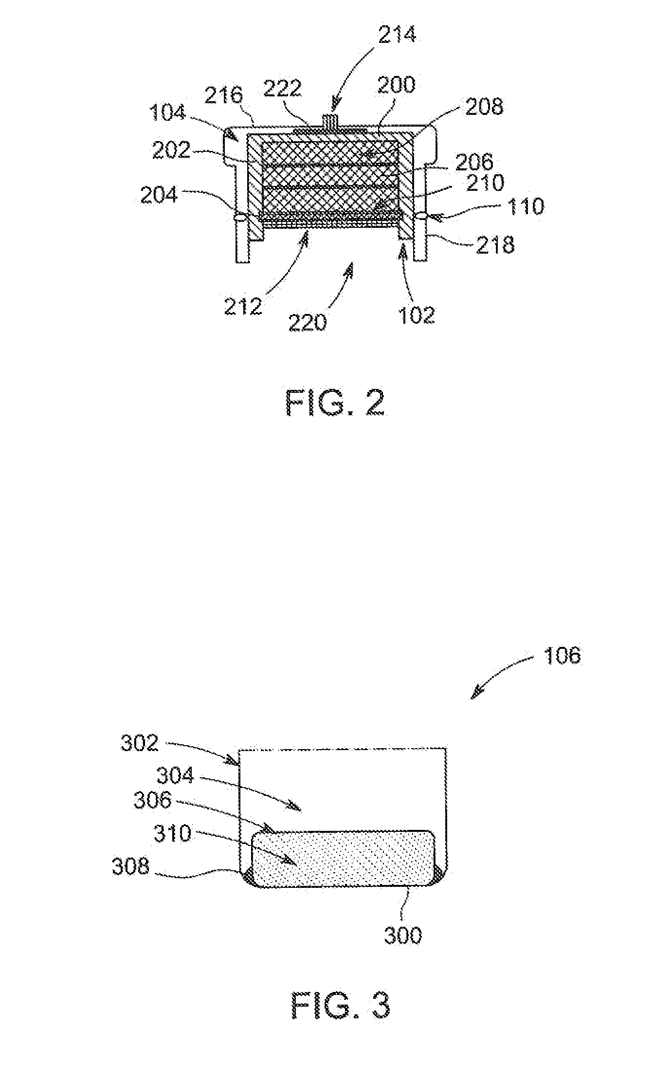
[0015]Embodiments of the present invention include a hydrogen gas generating apparatus. The hydrogen gas generating apparatus in accordance with embodiments of the present invention advantageously comprises separate components that can be easily transported and quickly assembled for use with any available water source, such as sea water, snow, drinking water, waste water, and urine. Separate components also help to maintain a long shelf-life by preventing the accidental formation of hydrogen gas. Upon assembly, the hydrogen gas generating apparatus immediately begins generating hydrogen gas with passive control of the hydrogen generation rate. The apparatus also advantageously provides passive control of hydrogen gas generation regardless of the orientation of the apparatus.

[0016]FIG. 1 depicts a schematic diagram of the assembly of a hydrogen gas generating apparatus 100 (hereinafter, the apparatus 100) in accordance with some embodiments of the present invention. The apparatus 100...


PUM

PropertyMeasurementUnit
volume ratioaaaaaaaaaa
pressureaaaaaaaaaa
volume ratioaaaaaaaaaa

Abstract

Apparatus for generating hydrogen gas are provided herein. In some embodiments, an apparatus for generating hydrogen gas may include a first chamber; a first mixture comprising a chemical hydride and a catalyst disposed within the first chamber; a second chamber coupled to the first chamber; a connector; a third chamber coupled by the connector to the second chamber, wherein the third chamber is fluidly coupled to the first chamber; a sealing element coupled to at least one of the second chamber or the third chamber; an outlet fluidly coupled to the first chamber; and a resilient member disposed within the third chamber and configured to control the flow of water into the first chamber via movement of the resilient member in response to hydrogen gas pressure within the apparatus.

Description

GOVERNMENT INTEREST[0001]Governmental Interest—The invention described herein may be manufactured, used, sold, imported and licensed by or for the U.S. Government.FIELD OF INVENTION[0002]Embodiments of the present invention generally relate to hydrogen gas generation, more particularly, to an apparatus for generating hydrogen gas.BACKGROUND OF THE INVENTION[0003]With the recent increase in portable electronics, there is an increasing demand on the electric power for such portable electronic devices. Fuel cell technologies have frequently been used to fulfill the high energy density requirements which current battery technologies are unable to meet. For example, a direct methanol fuel cell (DMFC) is a popular fuel cell technology for portable power applications. However, the DMFC is ill-suited as a wearable power source because it suffers from several problems, such as requiring an active battery for start-up, poor reliability and complicated system control, and low fuel to electric ...

Claims


Application Information

Patent Timeline
Patent Type & Authority Applications(United States)
IPC IPC(8): C01B3/06H01M8/06
CPCC01B3/065H01M8/04208H01M8/04216H01M8/065Y02E60/36Y02E60/50H01M8/0606
Inventor REN, XIAOMING
Owner UNITED STATES OF AMERICA THE AS REPRESENTED BY THE SEC OF THE ARMY
Why Eureka
Eureka Blog
Learn More