Hydrogen storage tank and method of using

a technology of hydrogen storage tank and storage tank, which is applied in the direction of liquid handling, instruments, packaged goods types, etc., can solve the problems of low heat value per volume, lack of convenience of gasoline, and difficulty in hydrogen storag

Active Publication Date: 2010-02-04
INDIANA UNIV RES & TECH CORP
View PDF3 Cites 38 Cited by
  • Summary
  • Abstract
  • Description
  • Claims
  • Application Information

AI Technical Summary

Problems solved by technology

However, hydrogen storage remains a challenge because of its very low heat value per volume compared to fossil fuels.
When compared to storage for conventional chemical fuels or electric energy sources, existing hydrogen storage technologies lack the convenience of gasoline for delivery and storage capacity (energy density per unit weight), and lack the flexibility of electrical energy stored in batteries and capacitors.
This method suffers two important drawbacks: carbon dioxide byproduct is a “greenhouse gas” that some believe contributes to global warming and is therefore environmentally undesirable; and the additional weight of the chemical molecule and the reformer reduce the efficiency of the entire process, making it less attractive from a cost and performance standpoint.
However, compressed gas cylinders are quite heavy, needing sufficient strength to withstand pressures of many thousands of pounds per square inch.
This weight is a considerable drawback for portable applications, and in any usage compressed gas cylinders must be treated with care because they represent a safety hazard.
Liquid hydrogen is remarkably dense from a specific energy point of view (kilowatts per kilogram), but requires a considerable amount of additional energy to maintain the nearly absolute zero temperatures needed to keep hydrogen in a liquid state.
Liquid hydrogen also requires a heavy mass of insulation, and these factors conspire to make cryogenic storage impractical for portable and small-scale applications.
However, prior hydrogen chemisorption techniques with these solid-state storage media have fallen short of the goals of efficiency, convenience, and low system cost for sev

Method used


Image

  • Hydrogen storage tank and method of using
  • Hydrogen storage tank and method of using
  • Hydrogen storage tank and method of using

Examples


Embodiment Construction

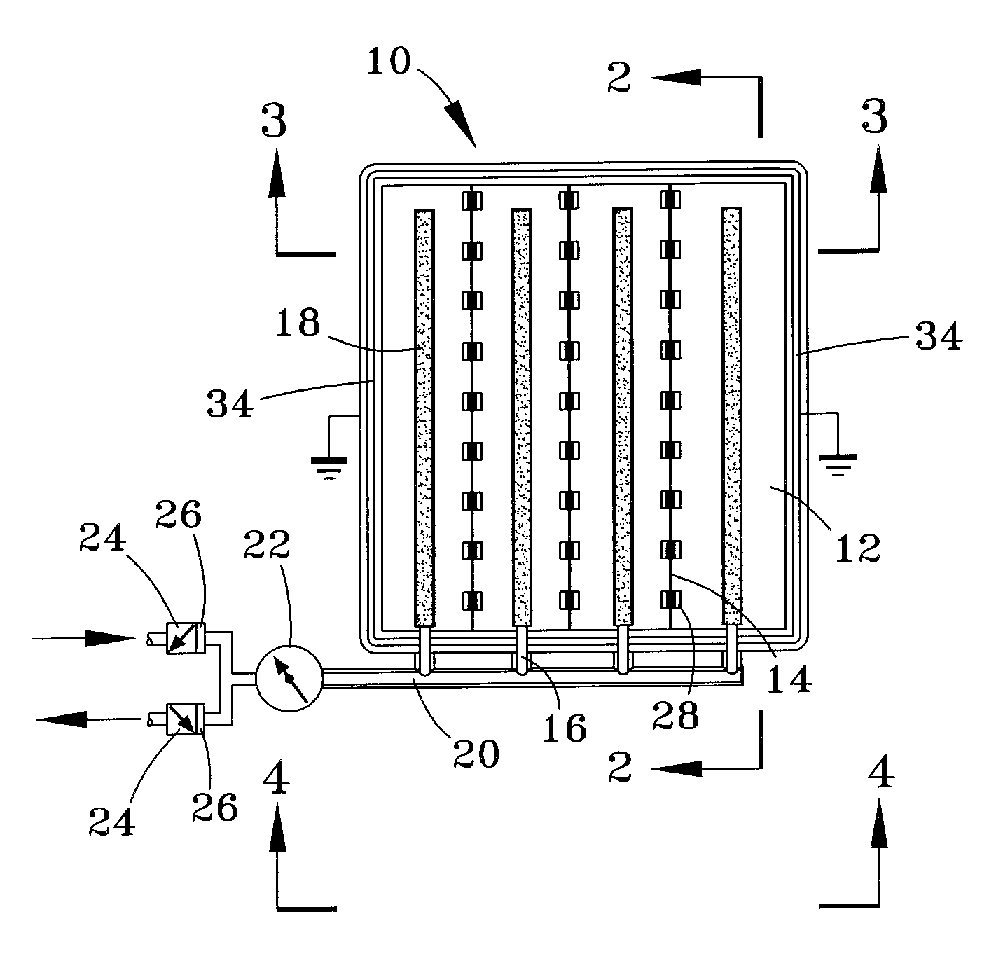
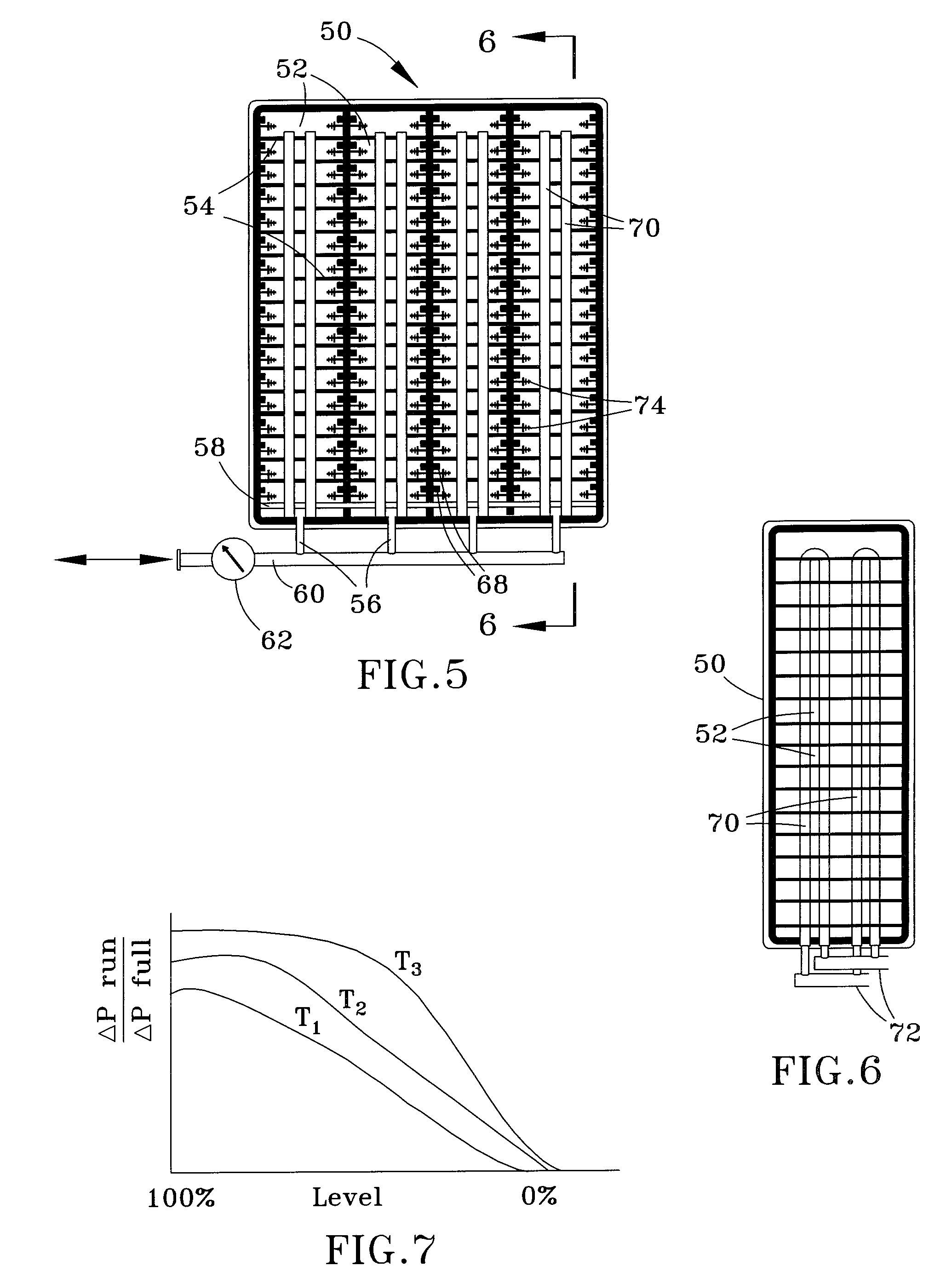
[0023]The present invention provides hydrogen storage systems with particular application for automotive fuel cells. The storage systems include integrated storage tanks adapted to contain solid-state storage media, including but not limited to nano-porous silicon (npSi) powders. The tanks are equipped with heat distribution systems, light sources, and electric field generators to facilitate hydrogen charge and discharge processes and fill level checks carried out with the tanks. An algorithm is preferably employed to determine the fill level of hydrogen in the tanks.

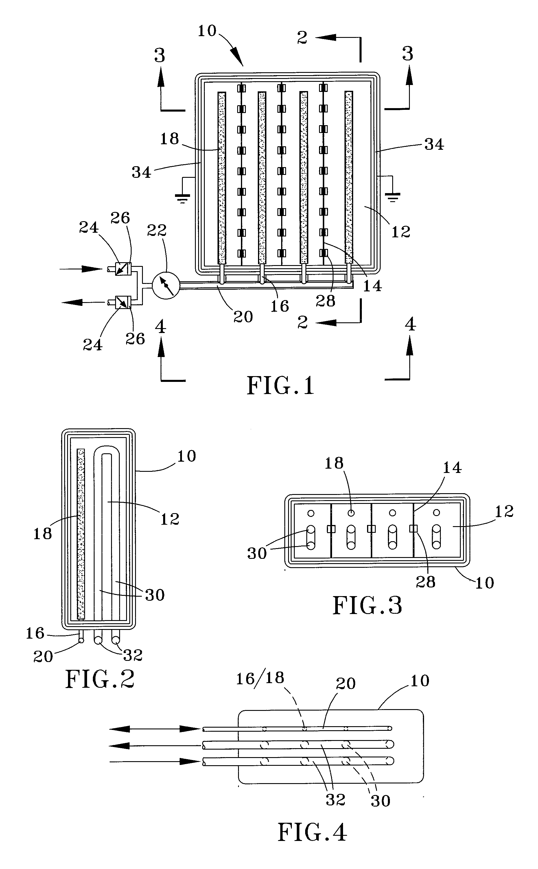
[0024]FIGS. 1 through 4 depict a first configuration of such a hydrogen storage tank 10. The tank 10 is divided into several compartments 12 by dividers 14 shown as extending the full height of the tank 10 so that the compartments 12 are substantially parallel to each other. Each compartment 12 is adapted to contain a solid-state storage media such as a npSi powder. The tank 10 is equipped with hydrogen inlet / outlet por...


PUM

PropertyMeasurementUnit
Temperatureaaaaaaaaaa
Pressureaaaaaaaaaa
Wavelengthaaaaaaaaaa

Abstract

A hydrogen storage tank for containing solid-state hydrogen storage media, and method for determining the hydrogen fill level in the tank. The tank has at least one compartment for storing the storage media, passages for transporting hydrogen gas to and from the compartment, and a heat distribution system for establishing a substantially uniform temperature in the storage media. A look-up table is generated for the tank that relates hydrogen pressure changes in the tank versus hydrogen fill levels in the tank as a function of temperature. The tank is filled to full capacity by adsorbing hydrogen on the storage media. Thereafter, hydrogen is released from the storage media for a time period during which there is a substantially constant demand on the tank, the change in pressure of the released hydrogen gas is measured, and the look-up table is applied to determine the hydrogen fill level in the tank.

Description

CROSS REFERENCE TO RELATED APPLICATIONS[0001]This application claims the benefit of U.S. Provisional Application No. 60 / 814,435, filed Jun. 16, 2006, the contents of which are incorporated herein by reference.STATEMENT REGARDING FEDERALLY SPONSORED RESEARCH[0002]This invention was made with United States Government support from Edison Materials and Technology Center (EMTEC), Contract No. EFC-H2-3-1C. The Government has certain rights in this invention.BACKGROUND OF THE INVENTION[0003]The present invention relates to hydrogen storage tanks and methods. More particularly, this invention relates to hydrogen storage tank adapted to contain solid-state hydrogen storage media, such as nano-porous silicon (npSi), and to methods for determining fill levels in such tanks.[0004]Hydrogen-based fuel cell technologies are being considered for a wide variety of power applications, including but not limited to mobile applications such as vehicles as an attractive alternative to the use of petroleu...

Claims


Application Information

Patent Timeline
IPC IPC(8): G01F23/00F17C11/00F17C5/06
CPCF17C11/005Y02E60/321G01F23/18G01F23/0076Y02P90/45Y02E60/32G01F23/804
Inventor YEN, DAVID W.ZHANG, JINGYINGSCHUBERT, PETER J.
Owner INDIANA UNIV RES & TECH CORP
Why Eureka
Try Eureka