
Bottom seismic system

Inactive Publication Date: 2014-07-03
KYASPER VLADIMIR EDUARDOVICH +3
View PDF16 Cites 5 Cited by
  • Summary
  • Abstract
  • Description
  • Claims
  • Application Information

AI Technical Summary

Benefits of technology

The present invention is a sea bottom seismic system that is designed to minimize the impact of magnetic masses on the compass' output indications and increase sensitivity. The system includes a vertical case made of non-magnetic material, a power supply unit, a main digital data processor, and a registration micro-processor. The bottom system also includes a multi-channel registration unit, an acoustic system, an angle-detector, a vacuum sensor, an external pressure sensor, and a communication unit for communication with a vessel that sets up and picks up the bottom system. The system is designed to provide maximum impact on the seabed and pick up after operation.

Problems solved by technology

Such design of the bottom system ensures a high technological suitability of the submerging—emerging operations, possibility of work at the depths up to 6000 meters, however, high positioning of transverse shear wave sensors relative to the bottom and elastic fastening of the system to the load reduces the system's sensitivity for the transversal waves.
However, it has a number of disadvantages, diminishing its efficiency.
Exemplarily, the rounding shape of cylindrical case reduces the area of contact with the sea bottom that affects accuracy of registration of transversal seismic waves.
Further, the prototype structure doesn't ensure minimization and correction of influence of magnetic masses of the bottom system's units on the compass' indications.
Another disadvantage of the aforementioned bottom system is absence of an acoustic system for determination of the system's coordinates on the seabed, which necessitates the use of an external acoustic navigation system.

Method used


Image

  • Bottom seismic system
  • Bottom seismic system
  • Bottom seismic system

Examples


Embodiment Construction

[0024]While the invention may be susceptible to embodiment in different forms, there are shown in the drawings, and will be described in detail herein, specific embodiments of the present invention, with the understanding that the present disclosure is to be considered an exemplification of the principles of the invention, and is not intended to limit the invention to that as illustrated and described herein.

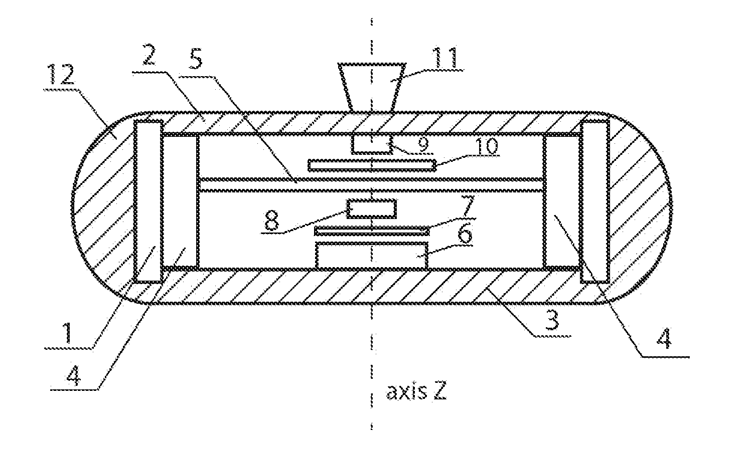
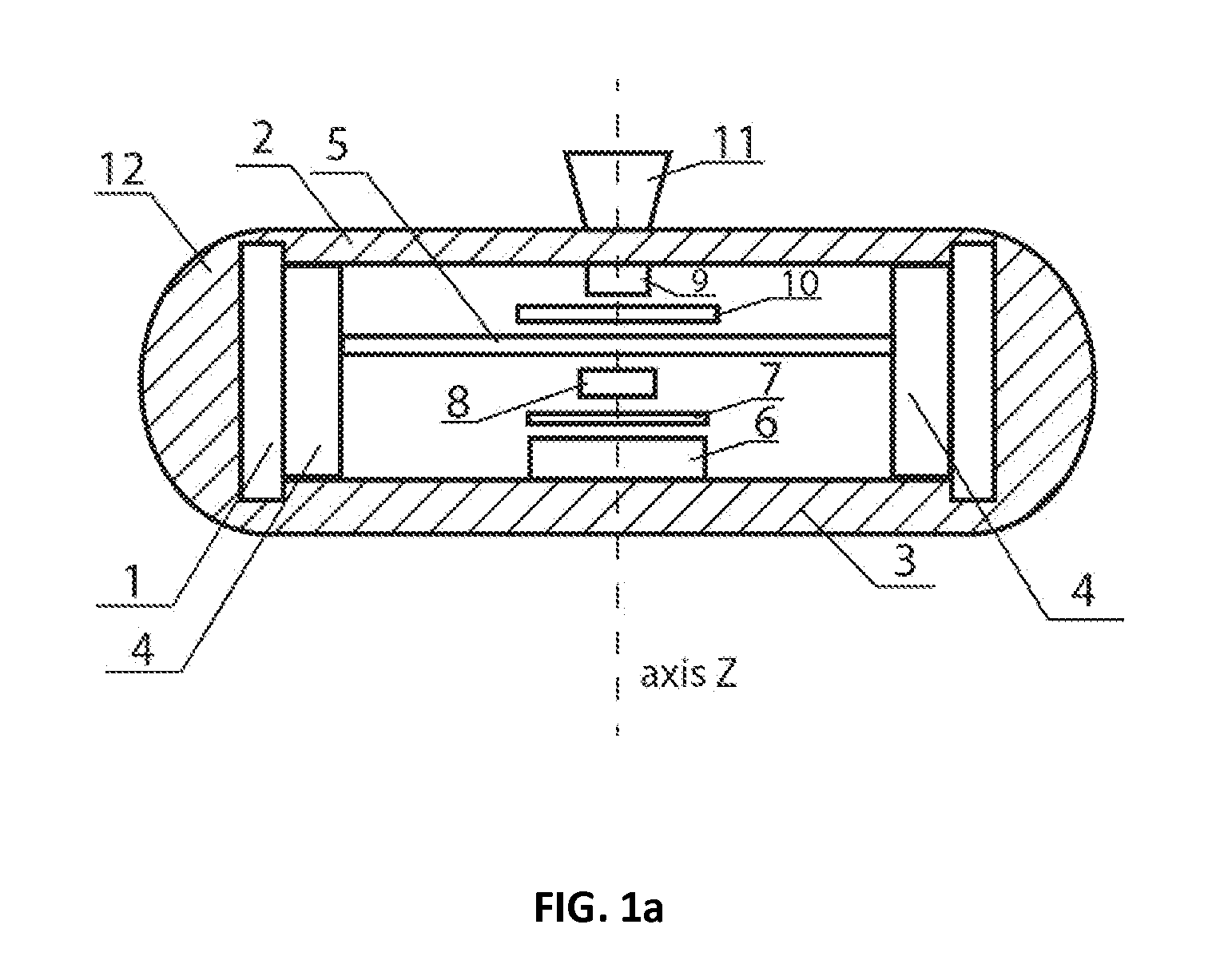
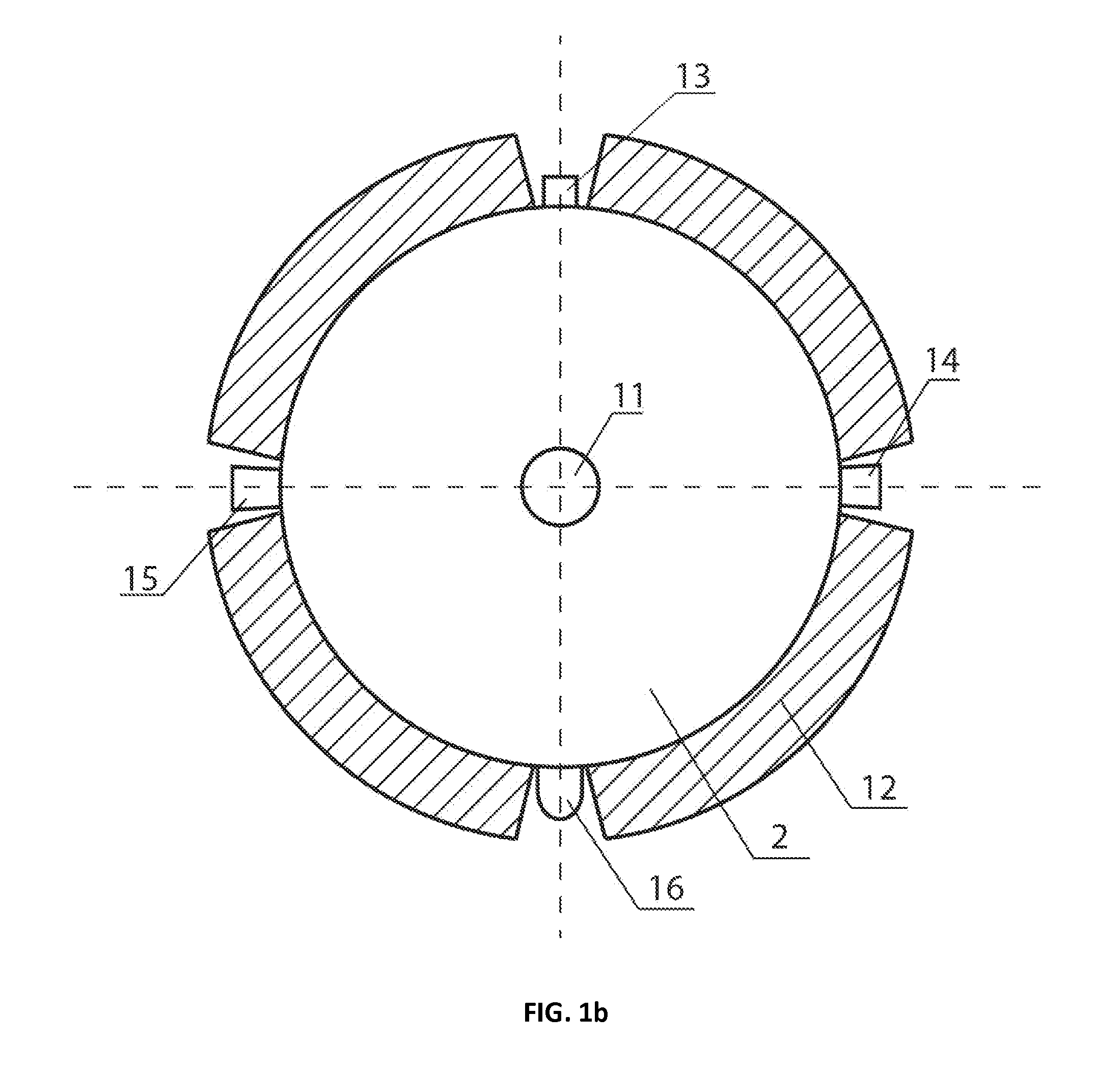
[0025]An exemplary preferred embodiment of the present invention is illustrated in FIGS. 1a and 1b, showing a general composition of the units of the inventive bottom system. FIGS. 2a and 2b schematically show a disposition of geophones, power supply batteries, and an angle-detector.

[0026]As shown in FIGS. 1a, 1b, 2a and 2b, the bottom system's units are designated the following reference numerals / letters: 1—a case of the bottom system, 2—an upper lid of the bottom system, 3—a bottom of the bottom system (in embodiments, the bottom 3 can be combined as a whole with the sidewalls...


PUM


Abstract

A sea bottom station for registration of seismic waves with vertical and horizontal components, having a vertical axis, including—a submergible case with a lid and a bottom preferably twice thicker than the lid,—a geophone block, wherein one geophone registers the vertical component, the remaining geophones register the horizontal component and create geophone pairs being pairwise orthogonal-positioned, while the geophones of each such pair are located symmetrically to the vertical axis. The bottom station includes—a power supply unit formed of rechargeable batteries, circumferentially located and pairwise symmetrical relatively to the vertical axis. The bottom station may include a multi-channel registration unit,—a connector socket, a LED sensor,—vacuum and external pressure sensors,—an acoustic system having an electronic board connected to an antenna,—an angle-detector associated with—a compass whose indication direction coincides with a geophone pair's axis, and the compass' center is located on the vertical axis.

Description

CROSS-REFERENCE TO RELATED APPLICATION[0001]This U.S. patent application claims priority under 35 U.S.C. 119 (a) through (d) from a Russian Federation patent application RU201258380 filed 28 Dec. 2012.FIELD OF THE INVENTION[0002]The proposed invention relates to the field of survey geophysics, in particular, to the equipment for multi-component seismic measuring at the sea bottom for prognosis of hydrocarbon deposits and study of the structure of sedimentary layer.BACKGROUND OF THE INVENTION[0003]Nowadays the seismic survey with the use of bottom systems, is rapidly developing, which allows for measuring not only longitudinal seismic waves, but also transversal seismic waves.[0004]There is known a bottom seismic system designed by a Russian state scientific-production enterprise <<Sevmorgeo>> (advertisement booklet of “Sevmorgeo”). The system is encapsulated in a spherical hermetic case, containing geophones, a power source, a registration unit, and a control unit of an ...

Claims


Application Information

Patent Timeline
IPC IPC(8): G01V1/38
CPCG01V1/3852
Inventor KYASPER, VLADIMIR EDUARDOVICHLISITSYN, EVGENY DMITRIEVICHEROFEEV, YURY GEORGIEVICHTULUPOV, ANDREJ VLADIMIROVICH
Owner KYASPER VLADIMIR EDUARDOVICH
Features
  • Generate Ideas
  • Intellectual Property
  • Life Sciences
  • Materials
  • Tech Scout
  • Unparalleled Data Quality
  • Higher Quality Content
  • 60% Fewer Hallucinations
Learn More