
Auto regulating gas system for supressed weapons

a gas system and automatic regulation technology, applied in the field of automatic gas regulation systems for firearms, can solve the problems of cyclic operation of weapons to speed up, and achieve the effect of reducing the volume of propellant gases and the amount of gas entering the system

Inactive Publication Date: 2014-07-17
REM TML HLDG LLC
View PDF2 Cites 8 Cited by
  • Summary
  • Abstract
  • Description
  • Claims
  • Application Information

AI Technical Summary

Benefits of technology

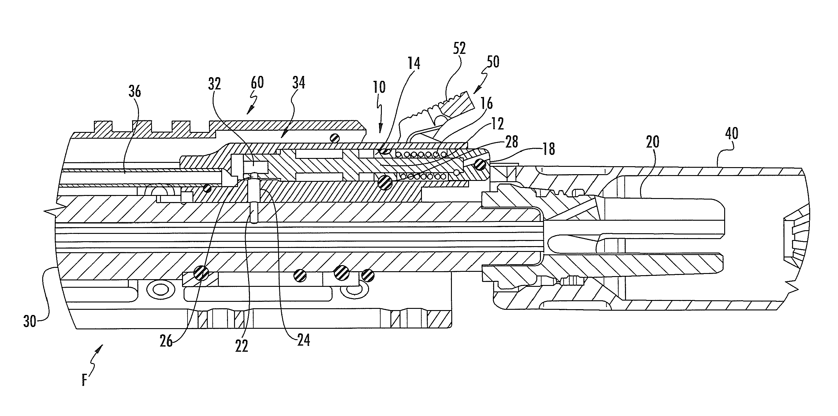
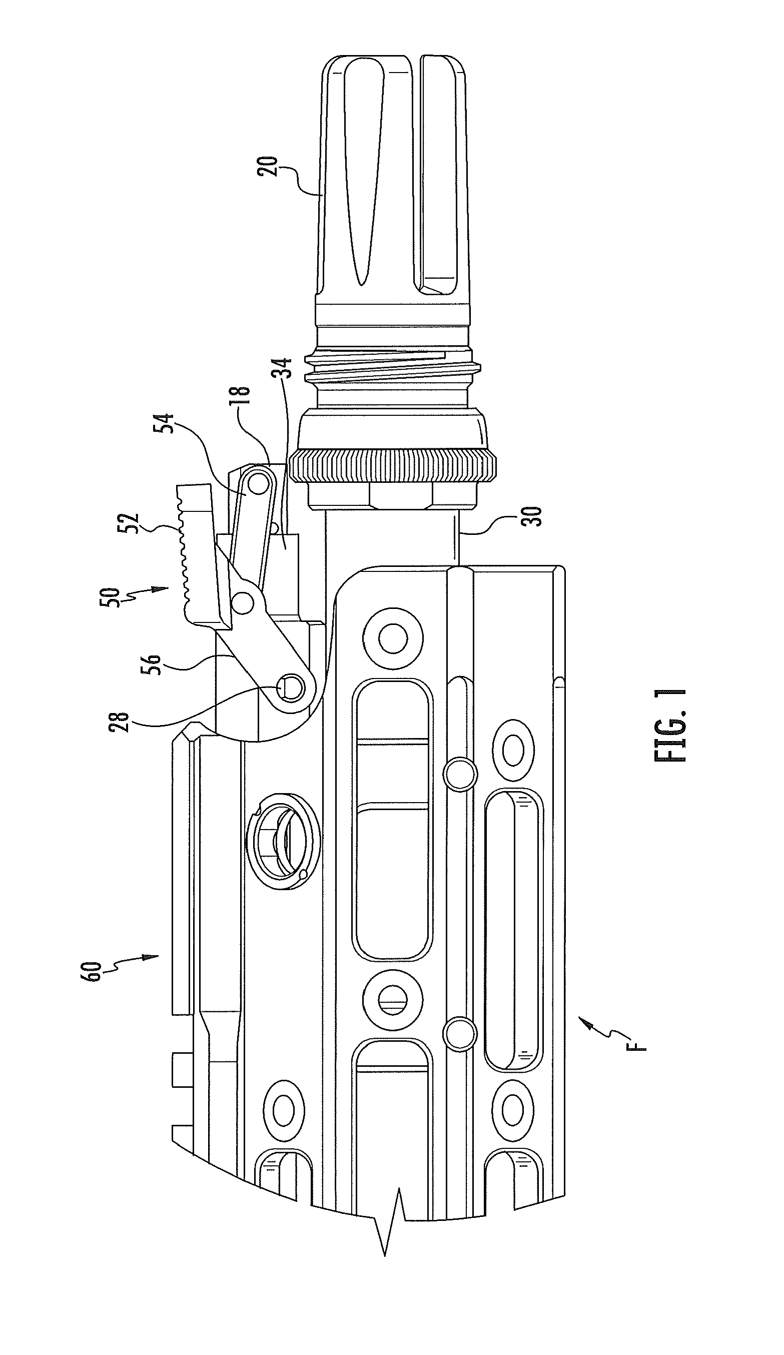
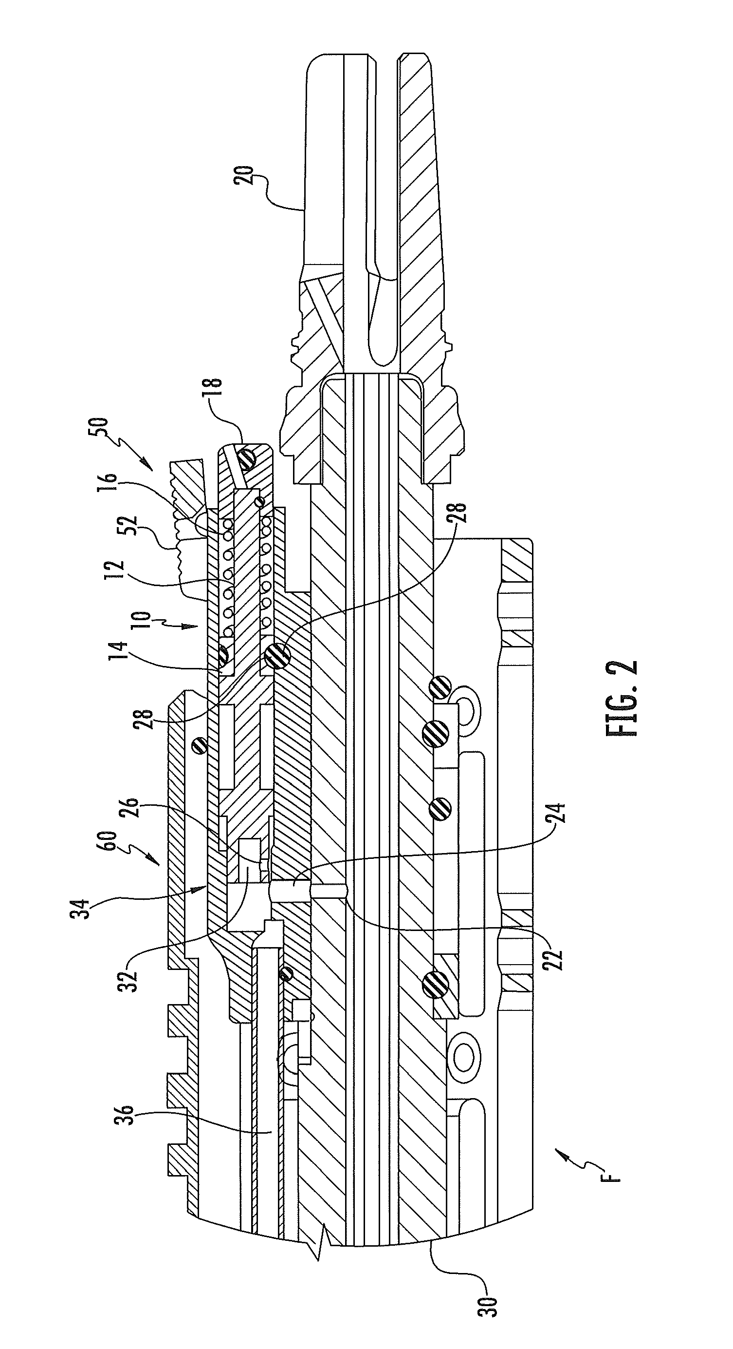
This patent is about a mechanism that regulates the speed of a weapon with a gas operating system by controlling the flow of gas. When a suppressor is installed, the mechanism automatically adjusts to match the speed of operation. This allows for smoother and safer use of autoloading firearms with suppressed silencers.

Problems solved by technology

In an autoloading firearm, installing a sound suppressor (silencer) on the weapon typically can cause the cyclic operation of the weapon to speed up due to residual pressures in the suppressor and bore of the weapon.

Method used


Image

  • Auto regulating gas system for supressed weapons
  • Auto regulating gas system for supressed weapons
  • Auto regulating gas system for supressed weapons

Examples


Embodiment Construction

[0020]The following description is provided as an enabling teaching of embodiments of the invention. Those skilled in the relevant art will recognize that many changes can be made to the embodiments described, while still obtaining the beneficial results. It will also be apparent that some of the desired benefits of the embodiments described can be obtained by selecting some of the features of the embodiments without utilizing other features. Accordingly, those who work in the art will recognize that many modifications and adaptations to the embodiments described are possible and may even be desirable in certain circumstances. Thus, the following description is provided as illustrative of the principles of the invention and not in limitation thereof, since the scope of the invention is defined by the claims.

[0021]There have been documented cases of weapon failing to operate when users fail to switch the weapons from unsuppressed to suppressed operation or vice versa when installing ...


PUM


Abstract

An auto regulating gas system to automatically regulate the operating speed of an auto loading weapon having a gas operating system by restricting the gas flow from the firing of a projectile. A gas block attached to the barrel or the weapon redirects a volume of propellant gases to cycle the weapon, the gas block including a gas port for directing propellant gases received from the a gas port of the barrel into the gas system. A spring-loaded plunger assembly is positioned within the gas block, the plunger assembly including a regulator plunger having a reduced flow orifice, a regulator bushing, a regulator spring, and a regulator cap, wherein the position of the regulator plunger within the gas block automatically controls an amount of gas that is allowed to enter the gas system. A mechanical backup linkage assembly is attached to the gas block as a backup device for returning the regulator plunger to a forward position in the gas block when a muzzle device mounted on a muzzle of the firearm is removed.

Description

CROSS-REFERENCE TO RELATED APPLICATION[0001]This application claims the benefit of U.S. Provisional Patent Application Ser. No. 61 / 751,625, filed on Jan. 11, 2013. The specification and drawings of the provisional patent application are specifically incorporated by reference herein. This application is related to co-pending and commonly assigned U.S. Application No. (Attorney Docket R087 2240US.1).TECHNICAL FIELD[0002]The present invention generally relates to gas operating systems for firearms and, more particularly, to automatic gas regulation systems for firearms.BACKGROUND OF THE INVENTION[0003]Semi-automatic firearms, such as rifles and shotguns, are designed to fire a round of ammunition, such as a cartridge or shotshell, in response to each squeeze of the trigger of the firearm, and thereafter automatically load the next shell or cartridge from the firearm magazine into the chamber of the firearm. During firing, the primer of the round of ammunition ignites the propellant (po...

Claims


Application Information

Patent Timeline
Patent Type & Authority Applications(United States)
IPC IPC(8): F41A5/28F41A33/00F41C27/06F41A21/30
CPCF41A5/28F41C27/06F41A33/00F41A21/30
Inventor KENNEY, DANIEL E.
Owner REM TML HLDG LLC
Learn More