Non-contact electrocardiogram system

a non-contact, electrocardiogram technology, applied in the field of electrocardiogram monitoring, can solve the problems of unworkable long-term personal health monitoring with traditional adhesive electrodes, unsuitable wires and adhesives, and considerable inconvenience and discomfort for users, so as to correct the gain dependence of the charge amplifier, and achieve the effect of robust and convenient heart rate monitor

Active Publication Date: 2014-07-17
UNIVERSITY OF ROCHESTER
View PDF2 Cites 19 Cited by
  • Summary
  • Abstract
  • Description
  • Claims
  • Application Information

AI Technical Summary

Benefits of technology

[0012]An embodiment of the invention provides a monolithic, non-contact ECG sensor system comprising electrodes and a charge amplifier based ECG sensor system integrated onto a single circuit board. In a non-limiting, exemplary aspect, four closely spaced electrodes were used to measure the ECG signal. This arrangement gives a robust and convenient heart rate monitor, however the interpretation of short base-line ECG measurements in more sophisticated morphological analysis of ECG signals must be done with care. In order to correct the gain dependence of the charge amplifier on the source capacitance, an aspect of the embodied invention employs a method in which the subject to electrode gap is continuously mo...

Problems solved by technology

Traditional adhesive sensor electrodes provide a stable, low impedance signal source that allow for the low noise measurement of ECG signals but the wires and adhesives employed are unsuitable for long term use; even common 24-48 hour Holter monitoring sessions are a considerable inconvenience and discomfort to the user so longer term personal health monitoring with traditional adhesive electrodes would be unworkable.
However, the presence of motion-related artifacts and common mode interference remains a challenging problem for several reasons.
First, interference from AC power mains may corrupt electrocardiograph signals due to low common mode rejection ratio (CMRR) of the sensor system.
Second, triboelectrically generated static charge caused by rubbing between the electrodes and the subject's clothing is another problem as is common mode electrostatic charge on the subject.
Third, the modulation of the bioelectric potential signals from motion-related source impedance changes presents a problem.
The signal gain may be a function of the source capacitance and any stray capacitance at the preamplifier input, which can lead to baseline wan...

Method used


Image

  • Non-contact electrocardiogram system
  • Non-contact electrocardiogram system
  • Non-contact electrocardiogram system

Examples


Embodiment Construction

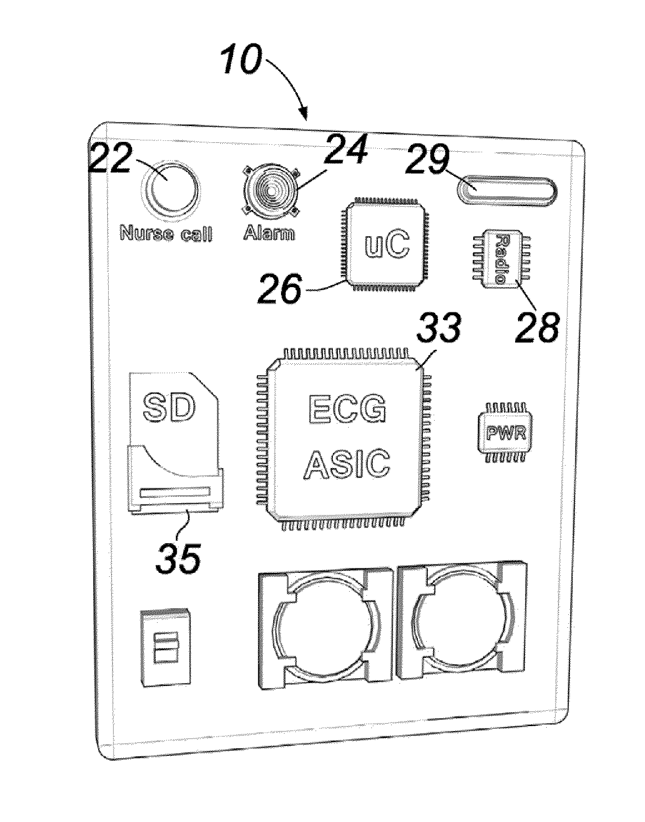
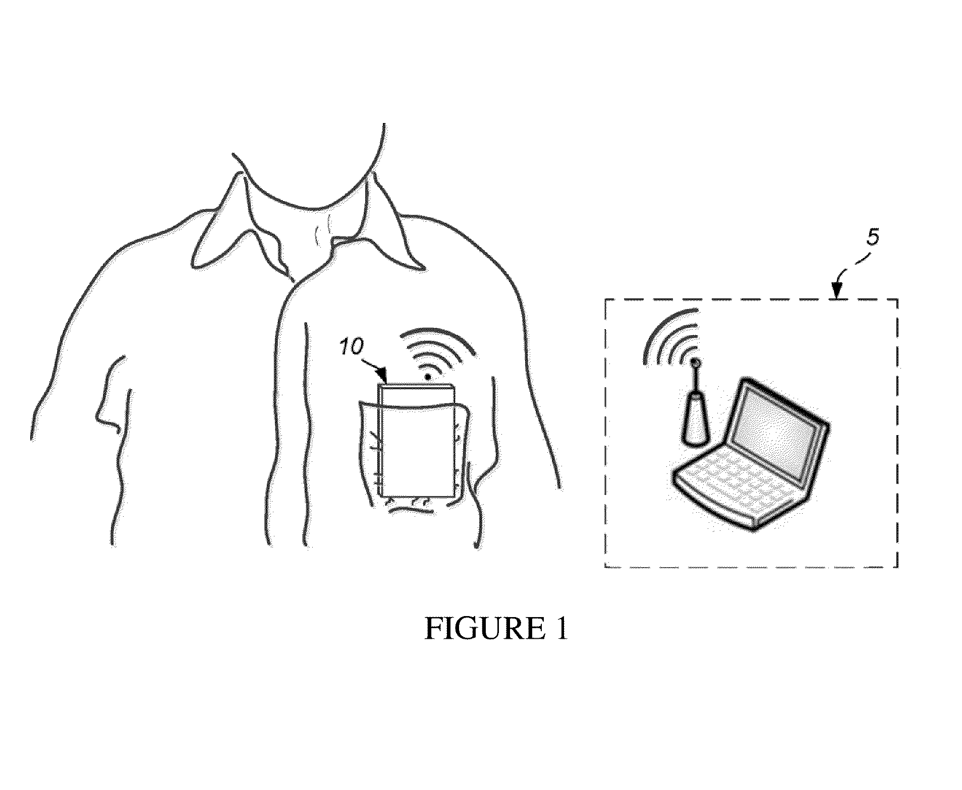
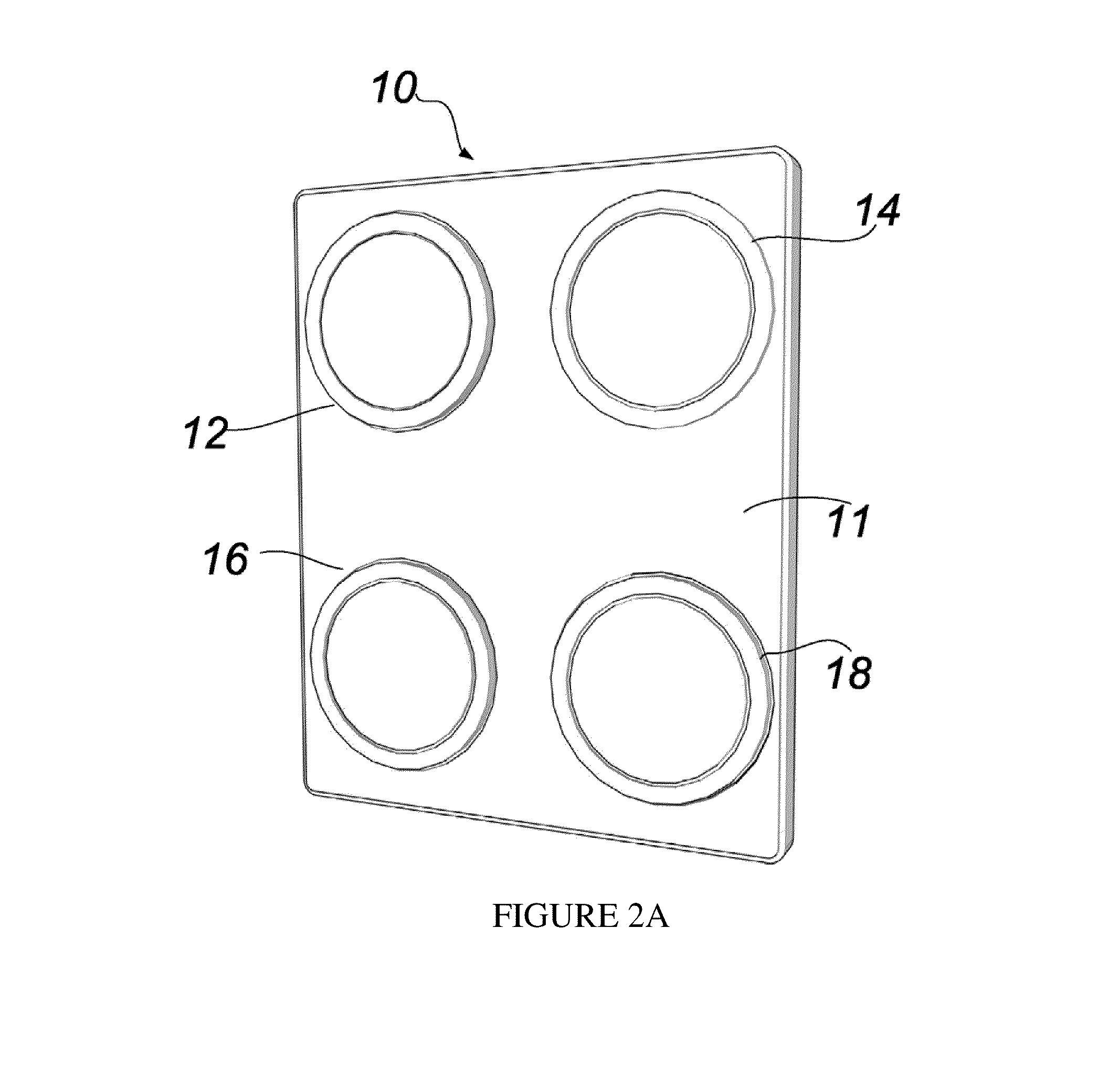
[0026]Referring now to the drawings, wherein like reference numerals refer to like parts throughout, there is seen in FIG. 1 a compact, credit card-sized sensor system 10 for measuring cardiac signals. The measured data can be wirelessly transmitted from system 10 to a user base station 5 for recording and analysis. System 10 includes four equally spaced and equal area cardiac sensors 12, 14, 16, and 18 as shown in FIG. 2A. The plane 11 is electrically shielded and grounded. System 10 further includes a front-end analog processing unit 33 labeled as ECG ASIC (Application Specific Integrated Circuit), a microcontroller 26, memory unit 35, radio communication circuit 28, antenna 29, power conditioning and power source unit and, optionally, an alarm (nurse call) button 22, and alarm speaker 24, as detailed in FIG. 2B.

[0027]An exemplary signal processing system 23 for system 10 is illustrated in FIG. 3. A sensor processor 20 is responsible for processing the signals from each of four ca...


PUM


Abstract

A non-contact electrocardiogram (ECG) sensor having an ECG electrode and guard electrode coupled to an electronic circuit that actively gain-corrects the electrocardiogram signal based on fringe capacitance signal and filters the gain-corrected signal based on a static charge reference signal. The compensation system first makes a gain correction for the preamplifier to address ECG electrode-to-subject motion and then removes any additive static common mode interference from motion-induced static charge generation.

Description

BACKGROUND OF THE INVENTION[0001]1. Field of the Invention[0002]The present invention relates to electrocardiogram monitoring and, more particularly, to non-contacting electrodes that may work through a subject's clothing.[0003]2. Description of the Related Art[0004]Sensors and systems for electrocardiogram (ECG) measurements have been developed and refined for many years. The front-end of all ECG systems consists of the sensor electrodes and preamplifiers. Traditional adhesive sensor electrodes provide a stable, low impedance signal source that allow for the low noise measurement of ECG signals but the wires and adhesives employed are unsuitable for long term use; even common 24-48 hour Holter monitoring sessions are a considerable inconvenience and discomfort to the user so longer term personal health monitoring with traditional adhesive electrodes would be unworkable.[0005]Non-contact biosensors for cardiac monitoring are of great interest for a number of long-term health sensing...

Claims


Application Information

Patent Timeline
IPC IPC(8): A61B5/00A61B5/0408A61B5/04A61B5/0245
CPCA61B5/721A61B5/0006A61B5/0245A61B5/746A61B5/04085A61B5/725A61B5/7405A61B5/04017A61B5/7214A61B2562/0214A61B5/316A61B5/282A61B5/346
Inventor BOCKO, MARK F.PENG, GUO CHEN
Owner UNIVERSITY OF ROCHESTER
Why Eureka
Try Eureka