Hierarchical multiscale fibrous scaffold via 3-d electrostatic deposition prototyping and conventional electrospinning

a fibrous scaffold and multi-scale technology, applied in the field of scaffolds, can solve the problems of weakening the mechanical strength of nanofibers, limited possibility to increase the pore size of nanofiber meshes or mats by manipulating fiber diameters, etc., and achieves the effect of large pore size and high surface area

Inactive Publication Date: 2014-07-24
STEVENS INSTITUTE OF TECHNOLOGY
View PDF18 Cites 20 Cited by
  • Summary
  • Abstract
  • Description
  • Claims
  • Application Information

AI Technical Summary

Benefits of technology

[0005]An embodiment of the present invention provides a 3-D multiscale fibrous scaffold comprising patterned layers of microfibers and one or more layers of nanofibers between layers of microfibers. In embodiments of the scaffold, the patterns are ordered patterns of microfibers (e.g., parallel microfibers). In embodiments of the invention, adjacent layers of microfibers are arranged in an antiparallel fashion. The scaffold of the present invention overcomes the current limitations of pore size and cellular infiltration present in nanofibrous mats, while keeping the advantages presented by nanofibrous mats, such as high surface areas for cellular adhesion and the advantages of microfibrous layered structured, such as large pore size for cellular infiltration and structural support for tissues grown on the scaffolds.

Problems solved by technology

One of the current challenges in tissue repair / regeneration is to fabricate a scaffold that will promote cell infiltration with the necessary cues for cell differentiation and appropriate mechanical support for tissue formation.
However, conventional electrospinning can only create dense mats of nanofibers with small pore size (e.g., pore sizes less than about 5 μm) which discourage cell infiltration.
Further, the opportunity to increase the pore size of nanofibers meshes or mats by manipulating fiber diameters is very limited.
The aforesaid methods, as they are presently applied, also weaken the mechanical strength of the nanofibers.

Method used


Image

  • Hierarchical multiscale fibrous scaffold via 3-d electrostatic deposition prototyping and conventional electrospinning
  • Hierarchical multiscale fibrous scaffold via 3-d electrostatic deposition prototyping and conventional electrospinning
  • Hierarchical multiscale fibrous scaffold via 3-d electrostatic deposition prototyping and conventional electrospinning

Examples


experimental examples

[0043]The following discussions present non-limiting examples of certain embodiments of the methods and scaffolds of the present invention. Persons having ordinary skill in the relevant arts and possession of the present disclosure may make numerous modifications and variations on these embodiments without departing from the spirit and scope of the invention.

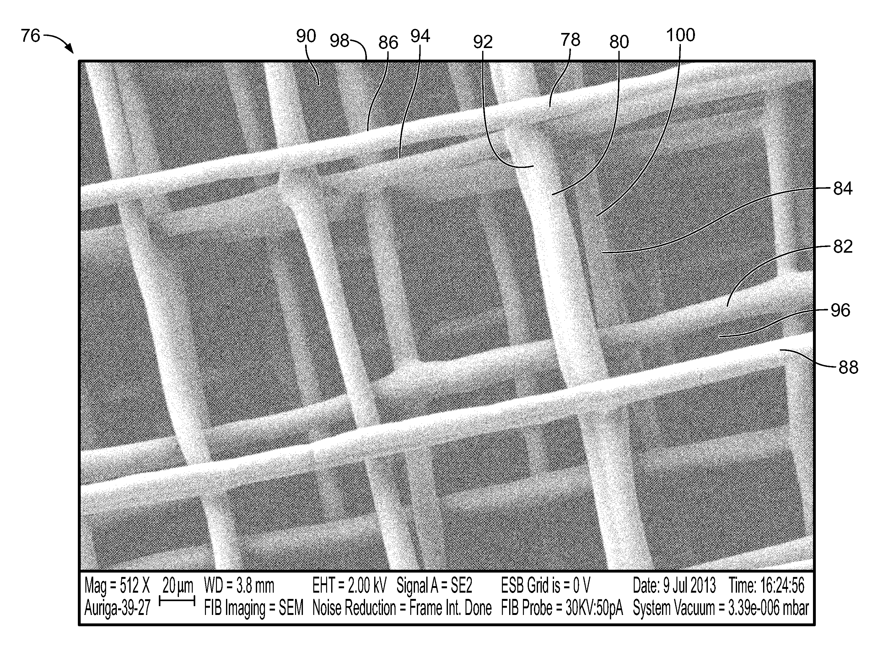
[0044]FIGS. 7-10 are microscopic images of scaffolds 62, 64 according to embodiments of the present invention. The scaffold 62 of FIGS. 7 and 8 consists of 44 layers of microfibers deposited in alternating antiparallel patterns (see, e.g, fiber 66 from a horizontal layer (relative to the orientation of the figure), and fiber 68 from an adjacent vertical layer). The interfiber spacing of the microfibers is about 200 μm, and the microfiber diameters are generally in the range of 10 μm to 20 μm. The scaffold 62 has a thickness of about 160 μm, and the microfiber diameters are generally in the range of 10 μm to 20 μm. The scaffold 6...


PUM

PropertyMeasurementUnit
diametersaaaaaaaaaa
diametersaaaaaaaaaa
diameteraaaaaaaaaa

Abstract

A hierarchical multiscale fibrous scaffold comprises multiple patterned layers of microfibers with one or more layers of nanofibers interleaved therebetween. In a method for making such scaffolds, electrodeposition or near-field electrospinning is used to deposit patterned layers of microfibers in a stack. Conventional electrospinning is used to deposit nanofibers on the layers of microfibers. The method may be used to tune the mechanical properties of the scaffold, facilitated by microfibers, and the biological features of the scaffold, facilitated by nanofibers. Scaffolds produced by such a process may have highly biomimetic architectures, and allow rapid cellular infiltration and sustainable cell growth for multiple tissue types.

Description

CROSS-REFERENCE TO RELATED APPLICATIONS[0001]The present application claims the benefit of U.S. Provisional Patent Application No. 61 / 754,203, filed on Jan. 18, 2013, the disclosure of which is incorporated by reference herein.FIELD OF THE INVENTION[0002]The present invention relates to scaffolds for implantable tissue grafts, and, more particularly, to hierarchical multiscale fibrous scaffolds for tissue growth that are produced by 3-D electrostatic deposition prototyping and conventional electrospinning.BACKGROUND OF THE INVENTION[0003]One of the current challenges in tissue repair / regeneration is to fabricate a scaffold that will promote cell infiltration with the necessary cues for cell differentiation and appropriate mechanical support for tissue formation. Evidence increasingly shows that nanofibers provide favorable environments for cell attachment and spreading, most likely as a result of their high surface area and their morphological and dimensional similarity to certain t...

Claims


Application Information

Patent Timeline
Patent Type & Authority Applications(United States)
IPC IPC(8): A61F2/02
CPCA61F2/02D04H13/00D01D5/0007D04H3/05A61L27/50D04H3/016D04H1/728D01D5/0084A61L27/56A61L2400/12D04H3/04
Inventor WANG, HONGJUNRICCARDELLO, GERALDLI, JIALE
Owner STEVENS INSTITUTE OF TECHNOLOGY
Why Eureka
Try Eureka