
System and process for hydrocracking and hydrogenation

a technology of hydrocracking and hydrogenation, applied in the field of hydrocracking or hydrogenation systems and methods, can solve the problems of inconvenient flaring, high cost, and high capital expenditure of steam reforming process, and achieve the effect of promoting free radical formation and free radical reaction, and promoting the formation of desired product distribution

Inactive Publication Date: 2014-07-31
HRD CORP
View PDF2 Cites 5 Cited by
  • Summary
  • Abstract
  • Description
  • Claims
  • Application Information

AI Technical Summary

Benefits of technology

The patent describes a process where a dispersion is made that is up to 50% supersaturated. This means that there is more of the desired product in the dispersion than what can be dissolved in it. This promotes the desired distribution of the product in the reaction. The high shear in the process helps create free radicals and promotes free radical reactions.

Problems solved by technology

The steam reforming process is capital intensive and thermally inefficient.
Many of the processes utilized in oil refineries create large quantities of gas.
A substantial quantity of this gas is negative-value gas, i.e. there is financial loss incurred in disposing of the gas.
Flaring may be undesirable due to environmental regulations.
Other types of negative-value gases (e.g., coker gas, hydrofinishing gas) are also most commonly flared, and thus not optimally utilized.
Often, due to the remote location of many oil fields, associated gas cannot be economically gathered from wells and transported to end-use applications and as a result is flared or in other instances vented to the atmosphere.
This is an environmental concern as flaring increases CO2 emissions and contributes to global warming and is a waste of natural resources.
Capturing and compressing natural gas (CNG) is expensive and requires significant energy for gas compression.

Method used


Image

  • System and process for hydrocracking and hydrogenation
  • System and process for hydrocracking and hydrogenation
  • System and process for hydrocracking and hydrogenation

Examples


Embodiment Construction

[0041]Overview.

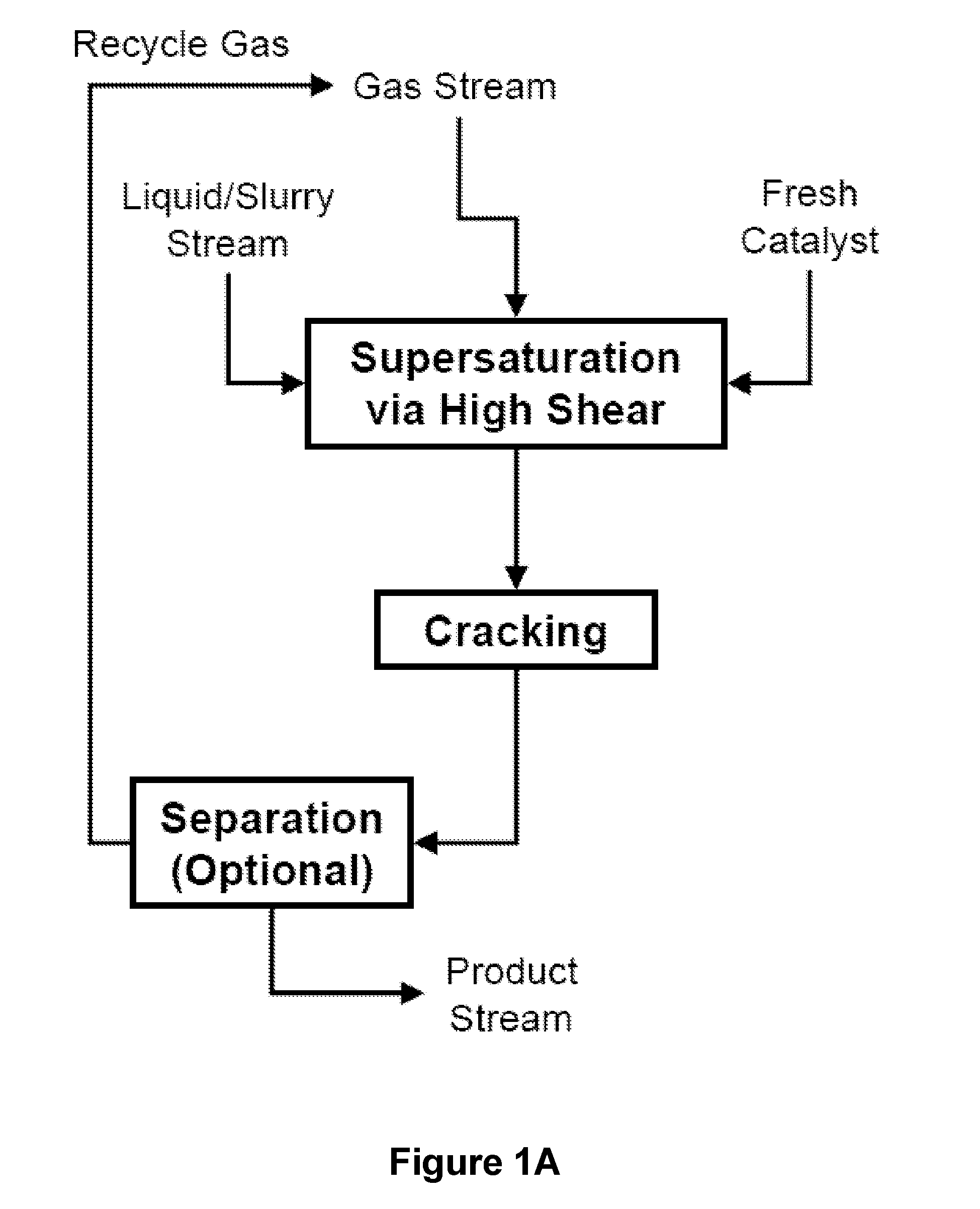
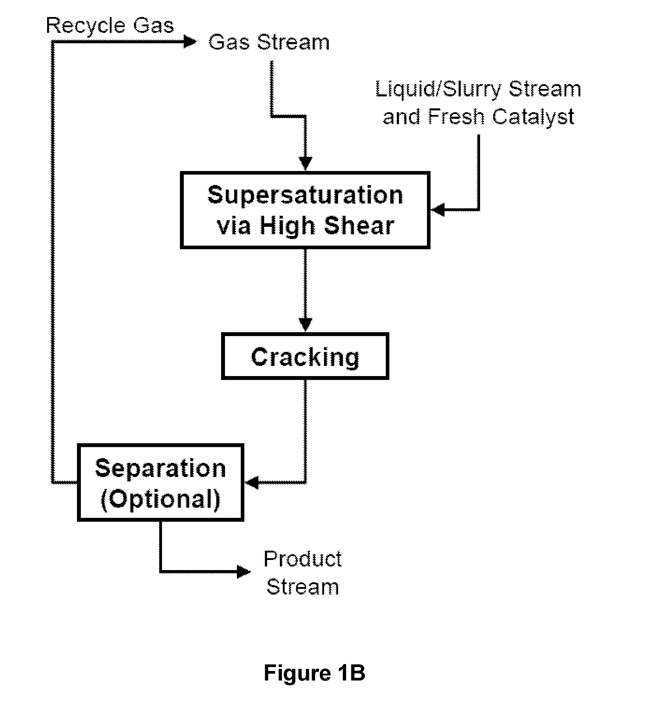
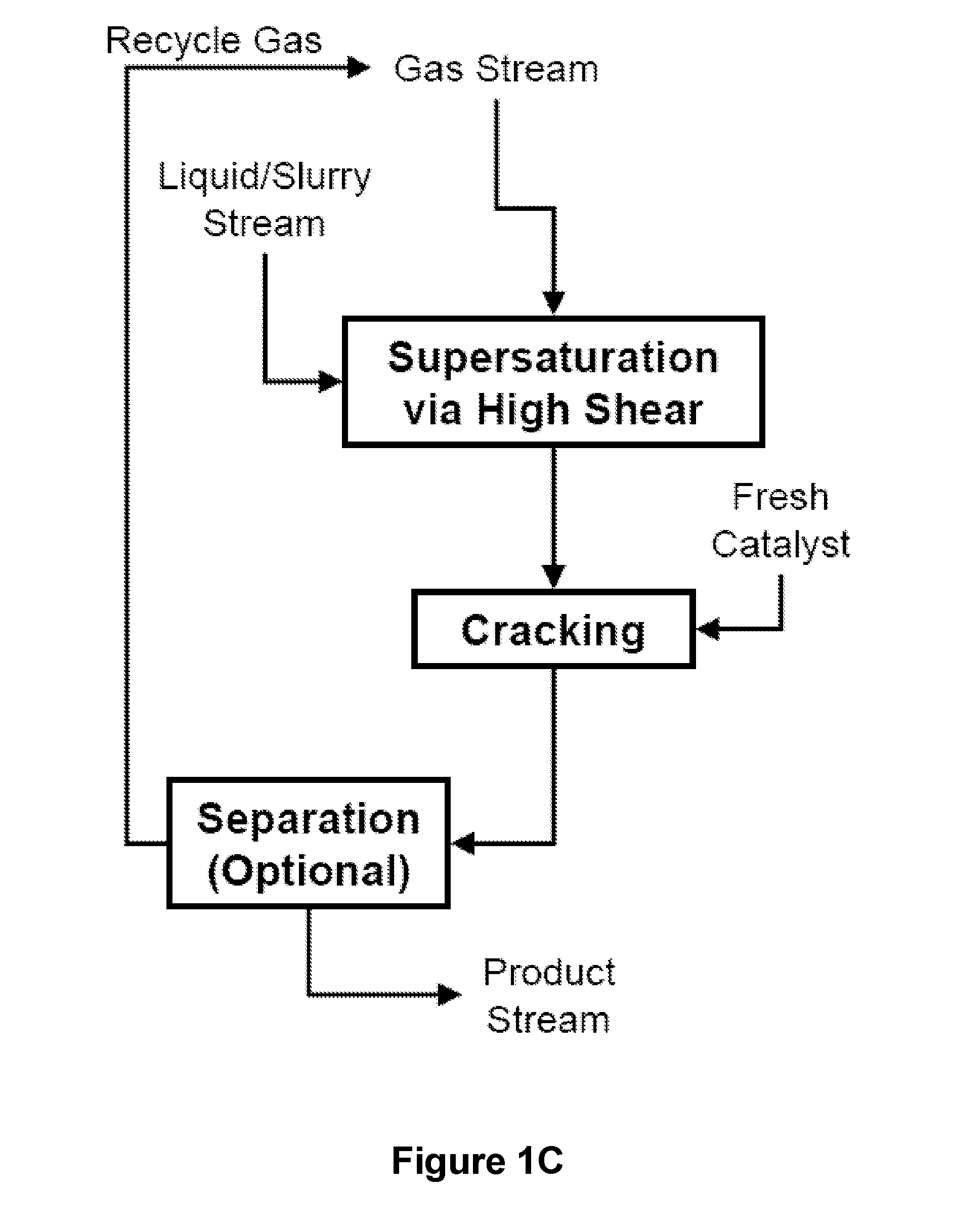
[0042]In various embodiments of this disclosure, as illustrated by FIGS. 1A-1C, a gas stream comprising hydrogen and optionally at least one or more hydrocarbons selected from C1-C6 is mixed with a liquid or slurry hydrocarbon stream in a high shear device to form a supersaturated dispersion. The supersaturated dispersion is then introduced into a cracking unit to produce a product stream under the action of a suitable catalyst. The product stream comprises improved product distribution of hydrocarbon compounds. In the case of hydrocracking, improved product distribution refers to a higher content of C3+ hydrocarbons compared to the totality of feed streams, including components for gasoline, diesel, jet fuel, asphalt base, heating oil, kerosene, and / or liquefied petroleum gas. In the case of hydrogenation, improved product distribution refers to a higher content of hydrocarbon saturation (i.e., single C—C bonds) and / or a lower content of impurities. In embodiments, t...


PUM

PropertyMeasurementUnit
speedaaaaaaaaaa
speedaaaaaaaaaa
speedaaaaaaaaaa

Abstract

Herein disclosed is a method for hydrogenation comprising: supersaturating a hydrocarbonaceous liquid or slurry stream in a high shear device with a gas stream comprising hydrogen and optionally one or more C1-C6 hydrocarbons to form a supersaturated dispersion; and introducing the supersaturated dispersion into a reactor in the presence of a hydrogenation catalyst to generate a product stream. In some embodiments, the catalyst is present as a slurry or a fluidized or fixed bed of catalyst. In some embodiments, the hydrogenation catalyst is mixed with the hydrocarbonaceous liquid or slurry stream and the gas stream in the high shear device. In some embodiments, the method further comprises recycling at least a portion of an off gas from the reactor, recycling at least a portion of the product stream from the reactor, or both. Also disclosed herein is a system for hydrogenation.

Description

CROSS-REFERENCE TO RELATED APPLICATIONS[0001]This application claims benefit of U.S. Provisional Application Ser. No. 61 / 756,890 filed on Jan. 25, 2013, entitled “System and Process for Hydrocracking and Hydrogenation,” incorporated herein by reference in its entirety for all purposes.STATEMENT REGARDING FEDERALLY SPONSORED RESEARCH OR DEVELOPMENT[0002]Not Applicable.BACKGROUND OF THE INVENTION[0003]1. Technical Field[0004]The present invention generally relates to a system and method of hydrocracking or hydrogenation that provides for improved product distribution of hydrocarbon compounds. More particularly, the present invention relates to supersaturating a liquid or slurry hydrocarbon stream with a gas stream comprising hydrogen in a high shear device to improve or induce hydrocracking reactions to produce a greater quantity of and / or a more desirable liquid product than would otherwise be produced.[0005]2. Background of the Invention[0006]Hydrogen is used in several petroleum an...

Claims


Application Information

Patent Timeline
Patent Type & Authority Applications(United States)
IPC IPC(8): C10G45/00F17D1/00
CPCF17D1/00C10G45/00C10G45/02C10G47/00B01J8/222B01J10/002B01J19/0066B01J19/1806B01J2219/0004B01J2219/00189C10G45/16C10G45/22C10G47/26C10G47/34C10G49/007C10G1/065Y10T137/0318B01F27/2711B01F33/811
Inventor HASSAN, ABBASHASSAN, AZIZANTHONY, RAYFORD G.BORSINGER, GREGORY G.
Owner HRD CORP
Learn More